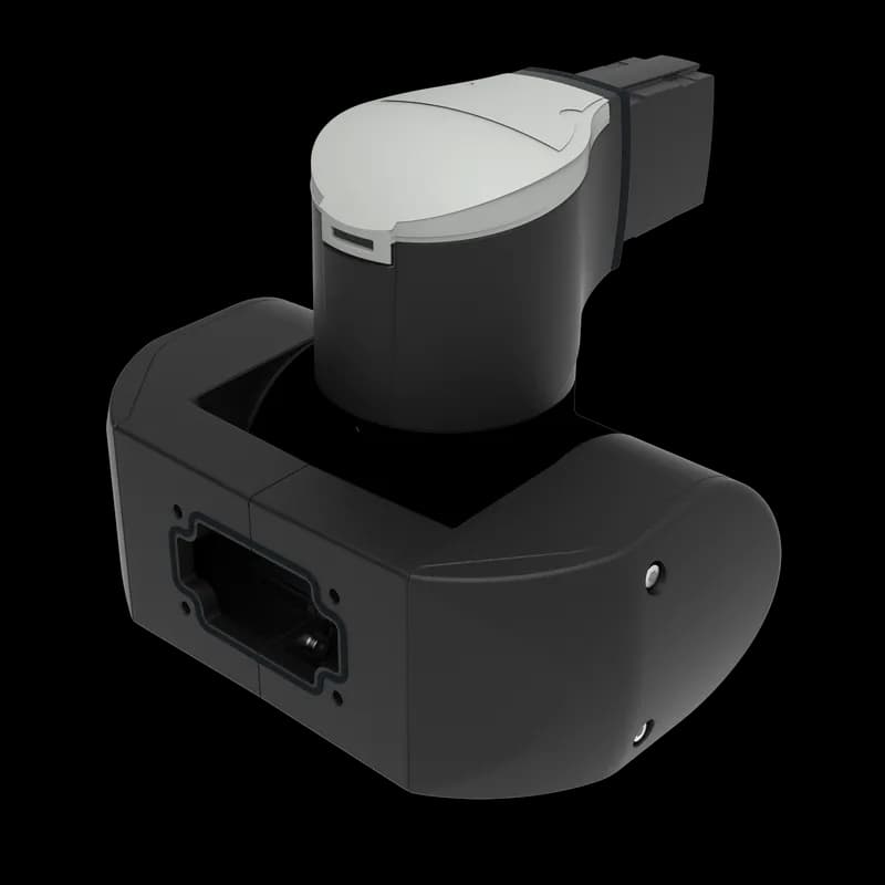
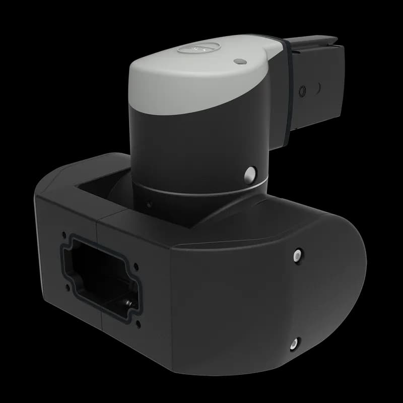
nVent S1MSCH Syspend 180-MAX Swivel Tilt Coupling Horizontal, 206x256x248, Jet Black, Aluminum
UPC: 783510593537
Contact for Pricing
Call +1 (262) 252-1600 (toll-free 877-268-3700) or email [email protected] for pricing and availability.
Overview
- 300-degree rotation with stop for precise positioning
- ±105-degree tilt with adjustable stop for ergonomic adjustments
- Durable aluminum construction with Jet Black powder-coated finish (RAL 7035)
- M6 and M10 hardware with lock actuators and lever clamps for vibration resistance
- Compatible with nVent Syspend 180-MAX system accessories
Specifications
Application | Controls and Drives |
Color | Jet Black |
Color Code | RAL 7035 |
Depth | 248 mm |
Depth | 9.76 in |
Finish | Powder Coated |
Height | 8.11 in |
Height | 206 mm |
Material | Aluminum |
Mounting Type | Top or Bottom Mounting |
Product Family | Syspend 180-Max |
Protection Rating | IP65 |
Series | Syspend 180-Max |
Size | 206x256x248 mm |
Type | Syspend 180-Max |
Weight | 11.18 lb |
Width | 256 mm |
Width | 10.08 in |
Package Dimensions (L x W x H) | 2 IN x 2 IN x 2 IN |
Package Dimensions (L x W x H) | 5.08 cm x 5.08 cm x 5.08 cm |
Package Weight (Imperial) | 2.000 L |
Package Weight (Metric) | 0.907 kg |
Frequently Asked Questions
What is the catalog number for the Syspend 180-MAX Swivel Tilt Coupling?
The catalog number for the Syspend 180-MAX Swivel Tilt Coupling Horizontal is S1MSCH.
What are the safety instructions for nVent products?
nVent products must be installed and used according to nVent's instruction sheets and training materials. Improper installation or misuse can lead to product malfunction, property damage, serious injury, death, and void the warranty.
What material is the Syspend 180-MAX coupling made from?
The Syspend 180-MAX Swivel Tilt Coupling is made from aluminum.
What is the weight of the Syspend 180-MAX Swivel Tilt Coupling?
The Syspend 180-MAX Swivel Tilt Coupling weighs 11.18lb.
What is the color code for the Syspend 180-MAX coupling?
The color code for the Syspend 180-MAX coupling is RAL 7035.
What are the dimensions of the Syspend 180-MAX Swivel Tilt Coupling?
The coupling has a height of 8.11 inches, a width of 10.08 inches, and a depth of 9.76 inches.
What is the color and finish of the coupling?
The coupling is Jet Black in color with a powder-coated finish.
What is the rotation and tilt angle range of the coupling?
The coupling offers a rotation angle of 300 degrees with a stop and a tilt angle of +/- 105 degrees with an adjustable stop.
What can the Syspend 180-MAX coupling be used to connect?
It allows for the connection of panels, displays, and enclosures that can be mounted from the top or bottom.
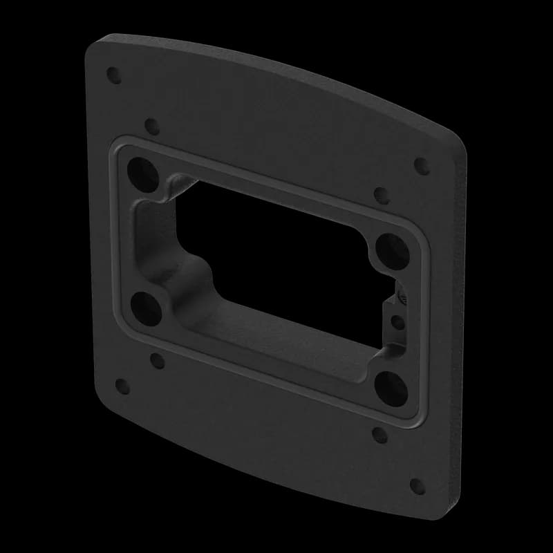
What type of mounting opening does the coupling have?
The coupling features a screwed mounting opening that is suitable for the feed-through of DVI connectors.
How to Install and Configure the SYSPEND 180-MAX Suspension System
This guide provides step-by-step instructions for the mechanical installation, tube mounting, component adjustment, and earthing of the SYSPEND 180-MAX suspension system, including specific guidance for components like the Vertical Panel Coupling (S1MPCV).
Estimated time: 1h 30m
Tools needed:
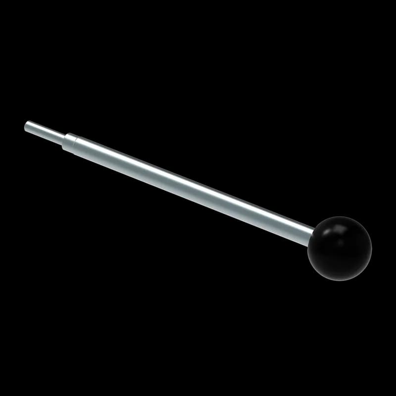
Wrenches (for M8, M6, M5 screws and SW27 nut), Screwdriver, Spirit level, Torque wrench, Special adjustment tool (item no. 980 5422 000)
Supplies needed:
Mounting screws (M8, M6, M5), Lock washers, Seals, Support tubes, Earthing conductor, Cable crimps, Serrated contact washers, Earthing continuity screw, Lock Actuator
- Mount the Suspension System Base to Plant or Machine
Ensure the mounting surface is smooth and flat to prevent issues with load, adjustment, and protection class. Secure the base component to the plant or machine using appropriate M8 or M9 screws. Use at least four bolting points as indicated in the diagrams.
- Install and Align Support Tubes
Smoothly press the seal into place on the component. Fit screws (1-6) into the support tube until they are flush with the inner surface. Push the support tube onto the component. Fit screws (1-2) until a noticeable resistance is felt; if the seal is not visibly crushed, press the tube further onto the component. Fit screws (5-6) and use a spirit level to check the vertical or horizontal alignment of the support tube. Finally, tighten screws (1-6) to 30 Nm. Do not damage seals during installation as otherwise the technical characteristics cannot be complied with.
- Mount the System to the Control Enclosure
Depending on the coupling type (Flange, Elbow, Narrow Adapter, or Panel Coupling), adhere the seal to the underside of the adapter or press it smoothly into place. Lift the control enclosure and support it under the coupling. Attach lock washers to the M6 or M5 screws. Fit the screws through the horizontal section into the coupling and tighten them to 6 Nm. Use at least four bolting points. For panel coupling components, ensure the mounting surface's stability is suitable. Off-center installation is not permitted.
- Adjust Tube Position and Component Firmness
To adjust the tube position, loosen screws (3-6). Tighten screws (5-6) for upward/downward adjustment or screws (3-4) for left/right adjustment until the desired position is reached. Then, tighten screws (3-6) to 30 Nm. To modify component firmness, adjust the clamping lever or the adjustment screw to increase or decrease resistance. Note that the factory preset is for optimum torque. Perform adjustments in the not installed condition of the components to ensure no bearing clearance.
- Perform System Earthing
Design the protective conductor system according to UL Standard UL 508A paragraph 14. Ensure the chosen cable length allows for all movements of the suspension system. Use the provided screw for a crimp-type socket, ensuring the screw length is suitable for the number of crimps. Separate each cable crimp with a serrated washer. Connect the earthing conductor using the earthing continuity screw and serrated washers, then tighten the screw to 2 Nm. Mounting or the electrical connection of the power line system must be carried out by a qualified electrician.
Frequently Asked Questions about nVent
What industries and applications are nVent products used for?
nVent products are engineered for critical infrastructure and industrial applications across multiple demanding sectors. Key markets include Construction, Data Centers, Defense, Healthcare, Mining, Oil & Gas Refineries, Power Plants, Rail/Transit, Renewable Energy, Security, Ship Building, Steel Mills, Telecom, and Utilities. Their solutions are designed to withstand extreme environmental conditions, with temperature ranges from -55°C to 105°C and specialized features like UV resistance, oil resistance, and flame resistance.
What environmental ratings do nVent products have?
nVent enclosures feature comprehensive environmental ratings, including UL 508A, CSA, and NEMA Type 1, 2, 3, 4, 4X, 12, and 13 certifications. They are rated IEC 60529 IP66, providing robust protection against dust, water, and corrosion in both indoor and outdoor environments. These products operate effectively in temperatures ranging from -40°F to 266°F, with enhanced UV inhibitors for outdoor weathering and oil-resistant gaskets for superior sealing.
What accessories are available for nVent products?
nVent offers a comprehensive range of accessories across multiple product lines, including EMC accessories like bonding cable clamps and strain reliefs, inline accessories such as lock inserts and mounting brackets, CONCEPT accessories including panel conversion kits and rack-mount angles, and seismic accessories for specialized mounting requirements. Key accessory categories include grounding kits, DIN rail mounting solutions, panel supports, handles, and various mounting hardware compatible with different enclosure types.
What certifications and standards do nVent products comply with?
nVent products meet critical international certifications including UL (United States), CSA (Canada), CE (European Community), and EAC (Russia). Our products are designed to comply with rigorous industrial standards such as NEMA enclosure ratings, IEC 60529 IP ratings, and international safety standards across multiple industrial markets including oil & gas, power, manufacturing, and infrastructure.
What is nVent's warranty policy?
nVent offers a standard 18-month warranty from invoicing date for most automation products, covering defects in workmanship and materials. The warranty requires proper transportation, handling, storage, and installation within specified environmental conditions. Warranty coverage includes repair or replacement at nVent's discretion, with certain conditions such as authorized service repairs and operation within designed capacity limits.
What technical support does nVent offer?
nVent offers comprehensive technical support through multiple global contact centers across North America, South America, Europe, Middle East, India, and Asia. Customers can reach technical experts by phone at regional numbers, with the North American headquarters in Minneapolis, MN providing primary support at +1.763.421.2240. Additionally, nVent provides online support resources through their website, including CAD drawing downloads and an 'Ask The Expert' feature to assist with product technical inquiries.