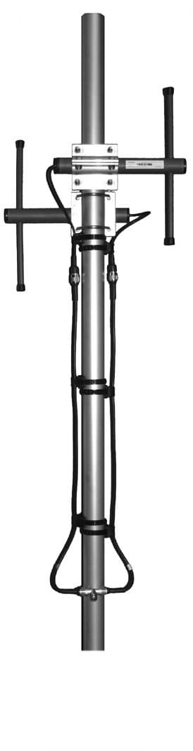
CompleTech CA450B2 - bidirectional broadside - Frequency range: 440-475 MHz - Gain: 6 dBi - Polarization: vertical - Connector: N-/TNC-female - VSWR: <1.5 - Radome: ABS/FG PU foam - Radiator material: copper - Mounting: 35-60 mm diameter pole - Wind load: 64 N
CompleTech

CA450B2


Documents & Media
Installation InstructionsSpecification Sheet

Contact for Pricing

Overview

The CompleTech CA450B2 is a bidirectional broadside antenna engineered for robust wireless communication solutions operating within the 440-475 MHz frequency range. This antenna is characterized by its 6 dBi gain, which facilitates strong signal propagation, and its vertical polarization, ensuring efficient signal transmission and reception. These attributes make it well-suited for demanding applications including industrial telemetry, SCADA systems, and security monitoring where reliable data transfer is paramount. The core of the CA450B2’s performance lies in its radiator, meticulously constructed from copper to guarantee optimal conductivity and signal integrity. For enhanced durability and protection against environmental elements, the antenna is housed within a radome composed of ABS and FG PU foam. A key performance metric, the VSWR, is maintained at less than 1.5, a critical factor for maximizing power transfer efficiency and minimizing detrimental signal reflections. Connectivity is facilitated by a versatile N-/TNC-female connector, offering broad compatibility with a wide array of radio systems and infrastructure. Installation is designed for simplicity and security, accommodating poles with a diameter ranging from 35 mm to 60 mm. Furthermore, the CA450B2 is built to withstand outdoor conditions, featuring a wind load rating of 64 N, which ensures stability and reliable operation even in exposed installations. This antenna presents a practical and dependable choice for fixed wireless deployments requiring consistent performance within its specified frequency band. Manufacturer: CompleTech. SKU: CA450B2. UNSPSC Code: 43221706.
  • Frequency Range: 440-475 MHz
  • Gain: 6 dBi
  • Polarization: Vertical
  • Connector: N-/TNC-female
  • VSWR: <1.5
  • Mounting: 35-60 mm diameter pole
  • Radome Material: ABS/FG PU foam
  • Radiator Material: Copper
  • Wind Load: 64 N

Specifications

Connection Type
N-/TNC-female
Connector
N-/TNC-female
Frequency
440-475 MHz
Gain
6 dBi
Length
390 mm
Material
ABS/FG PU foam, copper
Mounting Diameter
Ø 35-60
Mounting Type
35-60 mm diameter pole
Polarization
vertical
Radiator Material
copper
Radome
ABS/FG, PU foam
Series
CA450B2
VSWR
<1.5
Weight
1590 g
Wind Load
64 N @ 150 km/h
bidirectional broadside - Frequency range: 83-88 MHz - Gain: 6 dBi - Polarization: vertical - Connector: N-/TNC-female - VSWR: <1.5 - Radome: ABS/FG PU foam - Radiator material: copper - Mounting: 35-60 mm diameter pole - Wind load: 168 N

CA85B2

bidirectional broadside - Frequency range: 83-88 MHz - Gain: 6 dBi - Polarization: vertical - Connector: N-/TNC-female - VSWR: <1.5 - Radome: ABS/FG PU foam - Radiator material: copper - Mounting: 35-60 mm diameter pole - Wind load: 168 N
Antenna Combi 2x2 MIMO LTE/UMTS - GNSS. - EN50155 - IP67 - black

ANT-A-N3-CG-TRP-b

Antenna Combi 2x2 MIMO LTE/UMTS - GNSS. - EN50155 - IP67 - black
Wi-Fi antenna, screw mounted with 3m cable - RP-SMA

601-0005

Wi-Fi antenna, screw mounted with 3m cable - RP-SMA

How to Install the CA450B2 Controller

This guide provides step-by-step instructions for installing and configuring the CA450B2 Controller, ensuring proper wiring and calibration.

Estimated time: 1h

Tools needed:

Screwdriver, Wire strippers, Multimeter

Supplies needed:

Mounting screws, Wire connectors, Self-amalgamating tape

  1. Mount the controller

    Secure the CA450B2 controller to the designated mounting surface using the provided mounting screws. Ensure it is level and firmly attached.

  2. Connect the wiring

    Strip the ends of the wires and connect them to the appropriate terminals on the CA450B2 controller. Use wire connectors to ensure a secure connection.

  3. Seal the connections

    Cover all connectors and cable junctions with self-amalgamating tape to provide weather protection. Ensure that the tape is applied evenly and securely.

  4. Verify the installation

    Use a multimeter to check the voltage at the controller terminals to ensure proper power supply. Confirm that all connections are secure.

  5. Calibrate the controller

    Follow the manufacturer's instructions to enter the calibration mode and adjust the settings as required for your specific application.