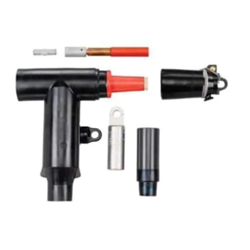
ABB Installation Products 656CEPTM0360DRG-S 15kV, 600 Amp - 200 Amp Combo T, with Insulated Cap and Sealing Kit. Combo Elbow with…
UPC: 075114369619
Contact for Pricing
Call +1 (262) 252-1600 (toll-free 877-268-3700) or email [email protected] for pricing and availability.
Overview
- 15kV rated deadbreak reducing tap with 600A/200A current rating
- Bi-metal compression lug supports 650-750 kcmil copper/aluminum conductors
- Insulation diameter range: 1.370-1.630 inches
- Reduces stack height by 2.67 inches for compact installations
- IEEE 386 color-coded PBT interfaces (red for 15kV) for easy alignment
Specifications
Amperage Rating | 600 A |
Application | 600 Amps, 15kV Connector |
Color | Black |
Conductor Range | 650 kcmil , 750 to 800 kcmil |
Connection Type | Bus, Stud, Cable Adapter, Lug Kit |
Current Rating | 600 A / 200 A |
Environmental Conditions | All Weather Conditions |
Insulation | True |
Material | Housing - EPDM-Rubber |
Material | Bi-Metal |
Size | 1.370 inch to 1.630 inch |
Special Features | Reducing Tap Plug with Stud, Cable Adapter, Lug and Insulated Cap |
Standard | ANSI/IEEE Standard 386 |
Temperature Rating, Maximum | 149 F |
Temperature Rating, Maximum | 65 C |
Temperature Rating, Minimum | -40 F |
Temperature Rating, Minimum | -40 C |
Type | ComboT Elbow |
Voltage Rating | 15 kV |
Width | 13.31 in |
Width | 338.074 mm |
Package Dimensions (L x W x H) | 0.01 IN x 0.01 IN x 0.01 IN |
Package Dimensions (L x W x H) | 0.0254 cm x 0.0254 cm x 0.0254 cm |
Package Weight (Imperial) | 1.0000 L |
Package Weight (Metric) | 0.4540 kg |

K655L3-LM0360
15/25kV 600 Series Deadbreak 3-Way L-Kit, Cable Insulation Diameter 1.280 inch to 1.430 inch. Aluminum Compression Lug. Conductor Size AWG or kcmil, Compressed Stranded 650 /Compacted Solid 750 /mmSquared Compact 400.
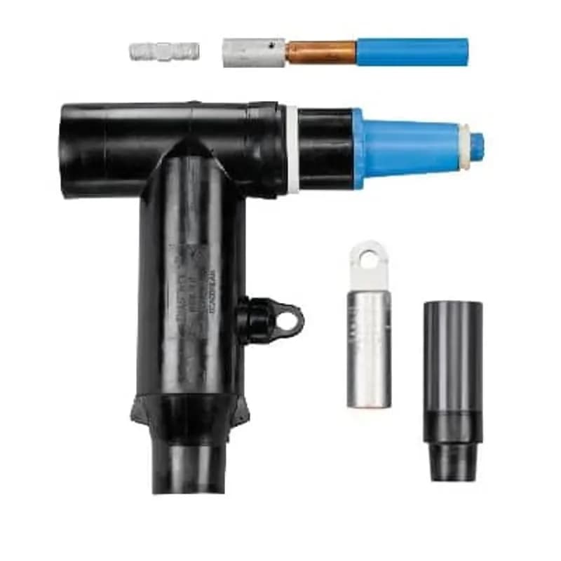
K656CETP-M0360
25kv, 600 Amp Series, Deadbreak Combo-T. Connector Elbow with Integral 200 Amp Loadbreak Tap Plug with Test Point. Cable Insulation Diameter 1.370-1.630 inches (34.8-41.4 mm). Aluminum Conductor Material, Conductor Code 360 - 650 Stranded/Compressed or 750/800 Solid/Compact. No Sealing Kit.K152SR-A0240
Straight Receptacle with Test Point, 200 Amp, DeadBreak, 15/25KV, Cable Insulation Diameter 0.575 inch to 0.740 inch. Aluminum Compression Lug. Conductor Size AWG Compressed Stranded 1/0, Solid 2/0.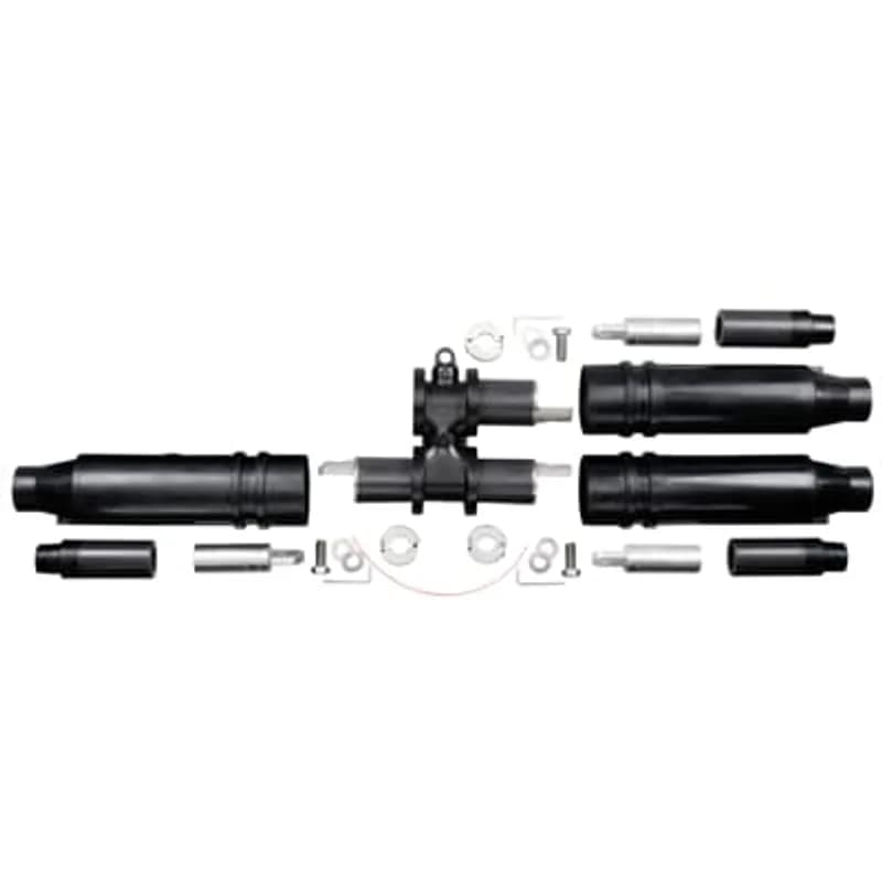
K656CY-DP0600536
600 Amp, 15/25 kV, Deadbreak Separable Y Joint package 3-Way with Test Point, (2) Sides Cable Insulation Diameter G - 0.760 inch to 0.950 inch. Aluminum Compression Lug. Conductor Size AWG Compressed Stranded 2/0 or Compacted Solid 3/0. (1) Side Cable Insulation Diameter K - 1.090 inch to 1.310 inch. Aluminum Compression Lug. Conductor Size kcmil Compressed Stranded 450 or Compacted Solid 550. Includes SG1 - Cold-Shrinkable Seal with Copper Rod and Crimp Connector.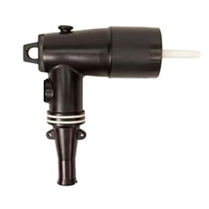
261LR-B5220
25/28kV, 200 Amp, Elbow Connector, Loadbreak, No Sealing Kit, No Test Point, Cable Insulation Diameter .635-.905 inches, Bi-Metal Lug, Conductor Size #2 Stranded/Compressed or #1 Compact/Solid.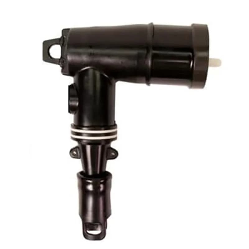
161LRJS-D5240
15KV, 200 Amp, Loadbreak Elbow with Sealing Jacket, Cable Insulation Diameter 0.890 inch to 1.220 inch. Bi-Metal Compression Lug. Conductor Size AWG Compressed-Stranded 1/0, Solid-Compact 2/0.K656CY-J0220
15-25kV 600 Series Deadbreak Separable Wye Joint Package (3-Way) with Test Point, Cable Insulation Diameter 0.980 inch to 1.180 inch. Aluminum Compression Lug. Conductor Size AWG Compressed Stranded #2 or Compacted Solid #1.Frequently Asked Questions
What is the maximum operating voltage for this product?
The product is rated for a 15kV voltage class, with a maximum phase-to-ground operating voltage of 8.3kV and a maximum phase-to-phase voltage of 14.4kV.
What are the continuous current ratings for the product?
The product has a 200 Amp continuous and loadbreak rating for the loadbreak interface, and a 600 Amp continuous rating for the deadbreak connection.
How do I choose the right compression lug?
Select the proper compression lug code (X code) from the X table according to the conductor size (AWG, kcmil, or mm2) to insert into the catalog number.
How do I select the correct cable insulation diameter?
Determine the cable's insulation diameter and select the W code from the table that best straddles this diameter to insert into the catalog number.
What is the impulse withstand rating?
The product has a 95kV BIL impulse withstand rating, based on a 1.2 x 50 μs wave.
Does the product meet industry standards?
Yes, the product meets ANSI/IEEE Standard 386, Latest Revision.
What is the maximum operating voltage for this product?
The product is rated for a 15kV voltage class, with a maximum phase-to-ground operating voltage of 8.3kV and a maximum phase-to-phase voltage of 14.4kV.
How do I choose the right compression lug?
Select the proper compression lug code (X code) from the X table according to the conductor size (AWG, kcmil, or mm2) to insert into the catalog number.
How do I select the correct cable insulation diameter?
Determine the cable's insulation diameter and select the W code from the table that best straddles this diameter to insert into the catalog number.
Does the product meet industry standards?
Yes, the product meets ANSI/IEEE Standard 386, Latest Revision.
How to Install 655/656/675/676CETP Deadbreak Elbow Connectors
This guide provides step-by-step instructions for the safe installation and wiring of 655/656/675/676CETP Deadbreak Elbow Connectors, ensuring proper cable preparation, lug crimping, and connection to mating apparatus. Follow all safety warnings for high voltage equipment.
Estimated time: 1h 30m
Tools needed:
Crimping tool, Wire brush, 600AT or 600ATM assembly tool (torque tool), Hotstick, Suitable voltage sensing device, Wire strippers, Utility knife, Measuring tape or ruler
Supplies needed:
655/656/675/676CETP Elbow, Cable Adapter, Compression Lug, Lubricant (silicone grease), Vinyl Plastic Tape, Tape Retainer (if applicable), Tape Marker (if applicable), 10TL cable shield adapter (if applicable), No. 14 AWG Copper wire (or equivalent) for grounding, Suitable ground connector, HV insulated cap(s) or connector(s), DR(G), ESA, GLR, or LR (if using tap plug interface)
- Perform Pre-Installation Checks and Safety Procedures
DANGER: All apparatus must be de-energized during installation. Inspect all parts for damage, rating, and compatibility. Remove any protective shipping covers and replace with appropriate HV insulated caps or connectors. Check package contents for completeness. Gather all required tools and maintain cleanliness throughout the procedure. This product should only be installed by competent personnel trained in high voltage electrical equipment safety practices.
- Position Cable and Make Initial Cut
Position the cable in its final assembled location, ensuring enough slack for elbow removal. If using concentric neutral cable, unwind the concentric neutral wires. Cut the cable 1-3/4 inches (45mm) from the centerline of the mating product.
- Clean Cable and Remove Outer Jacket
Clean the outer surface of the cable for a distance of 24 inches (610mm) or up to the bent-back concentric neutral wires. Remove the outer jacket to the dimension shown in the product's detailed diagrams. If using a 20MA/21MA grounding device or 600ECS Jacket Cable Seal, refer to their specific instructions for jacket removal and shield connection.
- Prepare Cable Shield (Type-Specific)
Follow the instructions applicable to your cable type: fold back shield wires; remove flat metallic tape shield and secure with vinyl plastic tape; remove fabric tape shield and install tape retainer and marker; remove longitudinally corrugated shield and install tape marker; for UNISHIELD® or lead sheath cable, refer to 10TL cable shield adapter instructions; remove semi-con shield and install tape marker. Do not cut or nick the cable insulation.
- Bevel Insulation and Install Cable Adapter
Bevel the end of the cable insulation at a 45-degree angle, approximately 1/4 inch (6mm) back. Thoroughly clean and then lubricate the cable insulation (using supplied lubricant), working towards the semi-con shield. Install the cable adapter, small end first, until it is flush with the edge of the tape marker.
- Prepare Conductor and Verify Length
Remove the protruding cable insulation by cutting it even with the end of the cable adapter. Exercise caution to avoid cutting or nicking the cable adapter or the conductor. Verify that the exposed conductor length is between 4-3/8 inches and 4-11/16 inches (111mm-119mm). If not, redo the assembly.
- Install and Crimp Compression Lug
For copper conductors, fully insert the conductor into the compression lug. For aluminum conductors, wire brush the conductor immediately before fully inserting it into the lug. Measure the 'Check Dimension' before crimping (must be less than 6-1/2 inches / 165mm). Crimp the lug according to its supplied instructions. Wipe off any excess inhibitor. Verify the distance from the lug end to the cable adapter is 6-1/2 to 7-1/4 inches (165mm-184mm) after crimping.
- Install Elbow onto Cable Adapter
Lubricate the cable adapter and the inside of the elbow cable entrance with the supplied lubricant. Install the elbow onto the cable adapter until it cannot advance further. Ensure the cable adapter remains flush with the tape marker; reposition if necessary. Remove the tape marker.
- Prepare Mating Apparatus and Install Stud
DANGER: Do not connect or disconnect mating products while energized. Do not energize while disconnected. Remove protective caps from both the elbow and the mating part. Install the stud into the apparatus by hand until it is fully seated. Clean and lubricate both the elbow and the mating part with the supplied lubricant, ensuring surfaces remain clean.
- Connect Elbow to Mating Part
Push the elbow onto the mating part. For products dated September 30, 2013, or earlier, use the 600AT assembly tool to engage the hex broach and torque the contact assembly until the torque limiter ratchets (19-25 ft/lbs). For products dated October 1, 2013, or later, use the 600ATM assembly tool and tighten the contact assembly to 50-60 ft/lbs torque, but do not exceed 60 ft/lbs.
- Ground Cable Shield and Elbow
Insert one end of a No. 14 AWG Copper wire (or equivalent ampacity) through the grounding eye and twist to form a small loop, taking care not to damage the eye. Connect this wire to ground using a suitable connector. Ensure the cable shield is grounded according to grounding device instructions or an alternate method. It is recommended to waterproof the cable jacket at this point to prevent moisture ingress.
- Install Tap Plug Interface (Optional)
If using a tap, clean and lubricate the entire loadbreak interface and the DR(G), ESA, GLR, or LR of the appropriate voltage class with the supplied lubricant. Install the DR(G), ESA, GLR, or LR to the tap plug interface, following the specific instructions provided with those products.
- Verify Seating and Perform Voltage Test
Confirm complete assembly by ensuring no portion of the colored interface sleeve is visible when viewed from the side. If applicable, perform a voltage test using the integral capacitance test point. Remove the test point cap with a hotstick (peel off at an angle). WARNING: This is a capacitance device; do not use conventional voltage measuring equipment. Use a suitable sensing device designed for capacitive test points. Treat the elbow as energized until a 'no voltage' indication is confirmed by other means. Clean, lubricate, and replace the cap after testing.
Frequently Asked Questions about ABB - Installation Products
How are Thomas and Betts products typically installed?
Thomas and Betts products are installed using a variety of methods tailored to specific applications, including the use of flexible cords and cable fittings, non-metallic cable glands, and armored cable fittings. Proper selection of fittings is crucial to match the cable type and installation environment, ensuring durability and preventing physical damage. Tools such as the Blackburn® Comfort Crimp® and HEX-FLEX® systems enhance installation efficiency and reliability, reducing labor time and ensuring secure connections.
What accessories are available for Thomas and Betts products?
Thomas and Betts offers a comprehensive range of accessories for their products, including various cord and cable fittings, non-metallic cable glands, service entrance cable fittings, and armored cable fittings. Their accessories are designed to enhance installation efficiency and ensure compatibility with different cable types and environmental conditions, providing reliable connections for a wide array of applications.
What environmental ratings do Thomas and Betts products have?
Thomas and Betts products feature robust environmental ratings, including NEMA Type 1, 2, 3, 4, 4X, 12, and 13 certifications, as well as IEC 60529 IP66 protection. These ratings ensure that their products are designed to withstand harsh industrial environments, with capabilities to resist dust, water, and corrosion, and operate effectively in a wide temperature range.
What communication protocols do Thomas and Betts products support?
Thomas and Betts products support a wide range of industrial communication protocols, including Ethernet, DeviceNet, PROFIBUS, Modbus, CANopen, and others. This extensive compatibility ensures seamless integration and reliable communication across various industrial automation systems, catering to diverse application needs.
What are the key features of Thomas and Betts products?
Thomas and Betts products are known for their innovative designs, high performance, and compliance with industry standards such as the National Electrical Code and Underwriters' Laboratories. They offer a comprehensive range of rugged and reliable electrical fittings, including liquidtight and dust-tight connections, which enhance installation efficiency and reduce overall project costs. Their products are engineered for durability in harsh environments, ensuring long-term reliability and lower installed costs.
What are the main product lines offered by Thomas and Betts?
Thomas and Betts offers a comprehensive range of product lines including electrical connectors, cable management systems, grounding and bonding solutions, and industrial automation components. Their products are designed for durability and reliability in demanding industrial environments, ensuring optimal performance and safety across various applications.
What technical support does Thomas and Betts offer?
Thomas and Betts offers comprehensive technical support, including access to field application engineers for onsite training and installation assistance. Their technical support staff is available to address inquiries related to product specifications and installation practices, ensuring optimal performance and safety of electrical systems. Additionally, they provide a variety of training programs to enhance the knowledge and skills of users in the field.
What industries and applications are Thomas and Betts products used for?
Thomas and Betts products are utilized across various industries including electrical construction, industrial automation, telecommunications, and utilities. Their extensive range of cord and cable fittings, electrical boxes, and metal framing systems are designed for applications that require durability and reliability in harsh environments, ensuring optimal performance in both permanent and temporary installations.
What certifications and standards do Thomas and Betts products comply with?
Thomas and Betts products comply with critical international certifications including UL (Underwriters Laboratories), CSA (Canadian Standards Association), and CE (European Community). Our products are designed to meet rigorous industrial standards such as NEMA enclosure ratings and IEC 60529 IP ratings, ensuring safety and reliability across various industrial applications.
What are the main product lines offered by Ocal?
Ocal offers a comprehensive range of corrosion-resistant conduit systems, including PVC-coated conduit and fittings, conduit bodies, hazardous location fittings, and strut accessories. Their products are designed to provide superior corrosion protection, featuring a hot-dipped galvanizing process and UL listed Type 4X PVC-coated conduit bodies, ensuring durability in the most demanding environments.