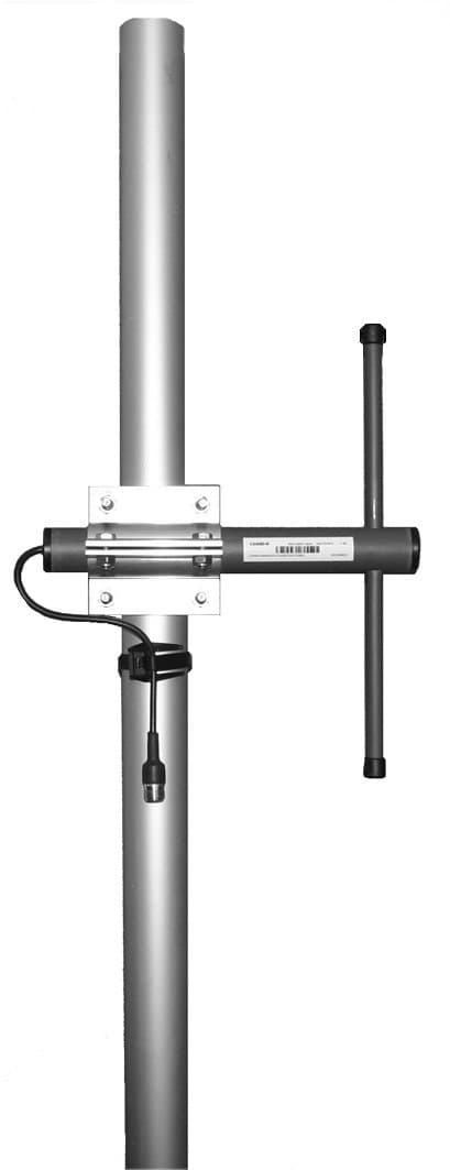
CompleTech CA450D offset pattern dipole - Frequency range: 440-475 MHz - Gain: 5 dBi - Polarization…
Documents & Media
Contact for Pricing
Call +1 (262) 252-1600 (toll-free 877-268-3700) or email [email protected] for pricing and availability.
Overview
- Offset pattern dipole antenna for 440-475 MHz frequency range
- 5 dBi gain with vertical/horizontal polarization
- Copper radiator for optimal signal conductivity
- Durable ABS/FG PU foam radome for environmental protection
- N-, TNC-, and 7/16-female connector compatibility
- Mounts on 35-60 mm diameter poles
- Low VSWR (<1.5) for efficient performance
- Rated for 32 N wind load
Specifications
Connector | N-/TNC-/7/16-female |
Frequency | 440-475 MHz |
Gain | 5 dBi |
Length | 275 mm |
Mounting Diameter | Ø 35-60 |
Polarization | vertical/horizontal |
Radiator Material | copper |
Radome | ABS/FG, PU foam |
VSWR | <1.5 |
Weight | 670 g |
Wind Load | 32 N @ 150 km/h |
CA420D
offset pattern dipole - Frequency range: 405-440 MHz - Gain: 5 dBi - Polarization: vertical/horizontal - Connector: N-/ TNC-/ 7/16-female - VSWR: <1.5 - Radome: ABS/FG PU foam - Radiator material: copper - Mounting: 35-60 mm diameter pole - Wind load: 33 N

CA160D
offset pattern dipole - Frequency range: 154-166 MHz - Gain: 5 dBi - Polarization: vertical/horizontal - Connector: N-/ TNC-/ 7/16-female - VSWR: <1.5 - Radome: ABS/FG PU foam - Radiator material: copper - Mounting: 35-60 mm diameter pole - Wind load: 57 N
CA170C4
offset pattern collinear - Frequency range: 163-177 MHz - Gain: 11 dBi - Polarization: vertical - Connector: N-/TNC-female - VSWR: <1.5 - Radome: ABS/FG PU foam - Radiator material: copper - Mounting: 35-60 mm diameter pole - Wind load: 220 N
CA450C2
offset pattern collinear - Frequency range: 440-475 MHz - Gain: 8 dBi - Polarization: vertical - Connector: N-/TNC-female - VSWR: <1.5 - Radome: ABS/FG PU foam - Radiator material: copper - Mounting: 35-60 mm diameter pole - Wind load: 64 N
CA380C3
offset pattern collinear - Frequency range: 365-395 MHz - Gain: 10 dBi - Polarization: vertical - Connector: N-/TNC-female - VSWR: <1.5 - Radome: ABS/FG PU foam - Radiator material: copper - Mounting: 35-60 mm diameter pole - Wind load: 105 NCA420C2
offset pattern collinear - Frequency range: 405-440 MHz - Gain: 8 dBi - Polarization: vertical - Connector: N-/TNC-female - VSWR: <1.5 - Radome: ABS/FG PU foam - Radiator material: copper - Mounting: 35-60 mm diameter pole - Wind load: 66 NFrequently Asked Questions
What is the frequency range of the CompleTech CA450D antenna?
The CompleTech CA450D antenna operates within the 440-475 MHz frequency range.
What is the gain of the CA450D dipole antenna?
The CompleTech CA450D antenna provides a gain of 5 dBi.
What types of connectors does the CA450D antenna support?
The CA450D antenna is compatible with N-, TNC-, and 7/16-female connectors.
What is the radome material for the CompleTech CA450D?
The radome of the CompleTech CA450D is constructed from ABS/FG PU foam.
What is the mounting diameter range for the CA450D antenna?
The CA450D antenna is designed for mounting on poles with diameters ranging from 35 to 60 mm.
What is the VSWR rating for the CA450D antenna?
The CompleTech CA450D antenna has a VSWR rating of less than 1.5.
What is the wind load rating for the CA450D antenna?
The CA450D antenna is rated for a wind load of 32 N.
What is the radiator material of the CA450D antenna?
The radiator material for the CompleTech CA450D antenna is copper.
How to Install the CA450D Controller
This guide provides step-by-step instructions for installing and configuring the CA450D Controller, ensuring proper wiring and initial setup.
Estimated time: 1h
Tools needed:
Screwdriver, Wire strippers, Multimeter
Supplies needed:
Mounting screws, Wire connectors, Self-amalgamating tape
- Mount the controller
Secure the CA450D Controller to the designated mounting surface using the provided mounting screws. Ensure it is level and firmly attached.
- Connect the wiring
Use wire connectors to connect the power and signal wires to the appropriate terminals on the CA450D Controller. Refer to the wiring diagram for correct terminal assignments.
- Seal the connections
Cover all connectors and cable junctions with self-amalgamating tape to ensure proper weather protection and prevent moisture ingress.
- Verify the connections
Use a multimeter to check the voltage at the power terminals to ensure that the controller is receiving the correct voltage as specified in the manual.
- Configure the controller
Follow the manufacturer's instructions to program the CA450D Controller settings according to your application requirements.
- Calibrate the controller
Perform any necessary calibration procedures as outlined in the user manual to ensure accurate operation of the CA450D Controller.