
CompleTech CA340B4 bidirectional stacked broadside - Frequency range: 326-353 MHz - Gain: 9 dBi…
Documents & Media
Contact for Pricing
Call +1 (262) 252-1600 (toll-free 877-268-3700) or email [email protected] for pricing and availability.
Overview
- Bidirectional stacked broadside antenna with field adjustable pattern
- Frequency range: 326-353 MHz
- Gain: 9 dBi
- Polarization: Vertical/Horizontal
- Connector: N-female / TNC-female
- VSWR: <1.5
- Radome: UV resistant ABS/FG, RAL 7012, PU foam filling
- Radiator material: Copper
- Mounting: Ø 35-60 mm pole diameter
- IP67 rated construction for environmental protection
Specifications
Connector | N-/TNC-female |
Frequency | 326-353 MHz |
Gain | 9 dBi |
Length | 1415 mm |
Mounting Diameter | Ø 35-60 |
Polarization | vertical |
Radiator Material | copper |
Radome | ABS/FG, PU foam |
VSWR | <1.5 |
Weight | 3670 g |
Wind Load | 144 N @ 150 km/h |
CA85B4
bidirectional stacked broadside - Frequency range: 83-88 MHz - Gain: 9 dBi - Polarization: vertical - Connector: N-/TNC-female - VSWR: <1.5 - Radome: ABS/FG PU foam - Radiator material: copper - Mounting: 35-60 mm diameter pole - Wind load: 336 N


CA350C3
offset pattern collinear - Frequency range: 336-364 MHz - Gain: 10 dBi - Polarization: vertical - Connector: N-/TNC-female - VSWR: <1.5 - Radome: ABS/FG PU foam - Radiator material: copper - Mounting: 35-60 mm diameter pole - Wind load: 108 N
CA340N4
cardioid pattern notch - Frequency range: 326-353 MHz - Gain: 8 dBi - Polarization: vertical - Connector: N-/TNC-female - VSWR: <1.5 - Radome: ABS/FG PU foam - Radiator material: copper - Mounting: 35-60 mm diameter pole - Wind load: 144 N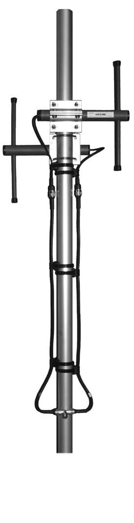
CA450B2
bidirectional broadside - Frequency range: 440-475 MHz - Gain: 6 dBi - Polarization: vertical - Connector: N-/TNC-female - VSWR: <1.5 - Radome: ABS/FG PU foam - Radiator material: copper - Mounting: 35-60 mm diameter pole - Wind load: 64 NCA380B2
bidirectional broadside - Frequency range: 365-395 MHz - Gain: 6 dBi - Polarization: vertical - Connector: N-/TNC-female - VSWR: <1.5 - Radome: ABS/FG PU foam - Radiator material: copper - Mounting: 35-60 mm diameter pole - Wind load: 70 NCA420N4
cardioid pattern notch - Frequency range: 405-440 MHz - Gain: 8 dBi - Polarization: vertical - Connector: N-/TNC-female - VSWR: <1.5 - Radome: ABS/FG PU foam - Radiator material: copper - Mounting: 35-60 mm diameter pole - Wind load: 132 NFrequently Asked Questions
What is the operating temperature range for the CA340B4 antenna?
The CA340B4 antenna can operate in temperatures ranging from -40 extdegree{}C to +80 extdegree{}C.
What is the impedance of the CA340B4 antenna?
The impedance of the CA340B4 antenna is 50 ohm.
What is the gain of the CA340B4 antenna?
The CA340B4 antenna has a gain of 9 dBi.
What type of connectors does the CA340B4 antenna use?
The CA340B4 antenna is available with N-female or TNC-female connectors.
What is the VSWR rating for the CA340B4 antenna?
The VSWR for the CA340B4 antenna is less than 1.5.
What materials are used for the CA340B4 antenna's radome?
The radome of the CA340B4 antenna is made of UV resistant ABS/FG with PU foam filling.
How is the CA340B4 antenna protected against lightning?
The CA340B4 antenna features DC-short circuited lightning protection.
What is the IP rating of the CA340B4 antenna?
The CA340B4 antenna has an IP67 rating, indicating dust and water protection.
What is the beamwidth of the CA340B4 antenna in the E-plane?
The E-plane beamwidth (-3 dB) for the CA340B4 antenna is 27 extdegree{}.
What is the beamwidth of the CA340B4 antenna in the H-plane?
The H-plane beamwidth (-3 dB) for the CA340B4 antenna is 71 extdegree{}.
How to Install the CA340B4 Controller
This guide provides step-by-step instructions for installing and configuring the CA340B4 Controller, ensuring proper wiring and calibration.
Estimated time: 1h
Tools needed:
Screwdriver, Wire strippers, Multimeter
Supplies needed:
Mounting screws, Self-amalgamating tape, Terminal connectors
- Mount the controller
Secure the CA340B4 controller to the designated mounting surface using the provided mounting screws. Ensure it is level and firmly attached.
- Connect the wiring
Use wire strippers to prepare the ends of the wires. Connect the appropriate wires to the terminal connectors on the CA340B4, ensuring correct polarity and secure connections.
- Seal the connections
Cover all connectors and cable junctions with self-amalgamating tape to provide weather protection. Ensure that all exposed areas are thoroughly covered.
- Verify connections
Use a multimeter to check the voltage and continuity of the connections. Ensure that all readings are within the specified range for proper operation.
- Calibrate the controller
Follow the manufacturer's instructions to enter the calibration mode on the CA340B4. Adjust the settings as necessary to match the operational requirements.