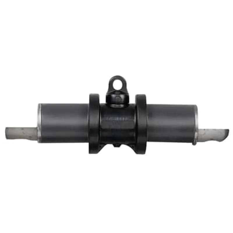
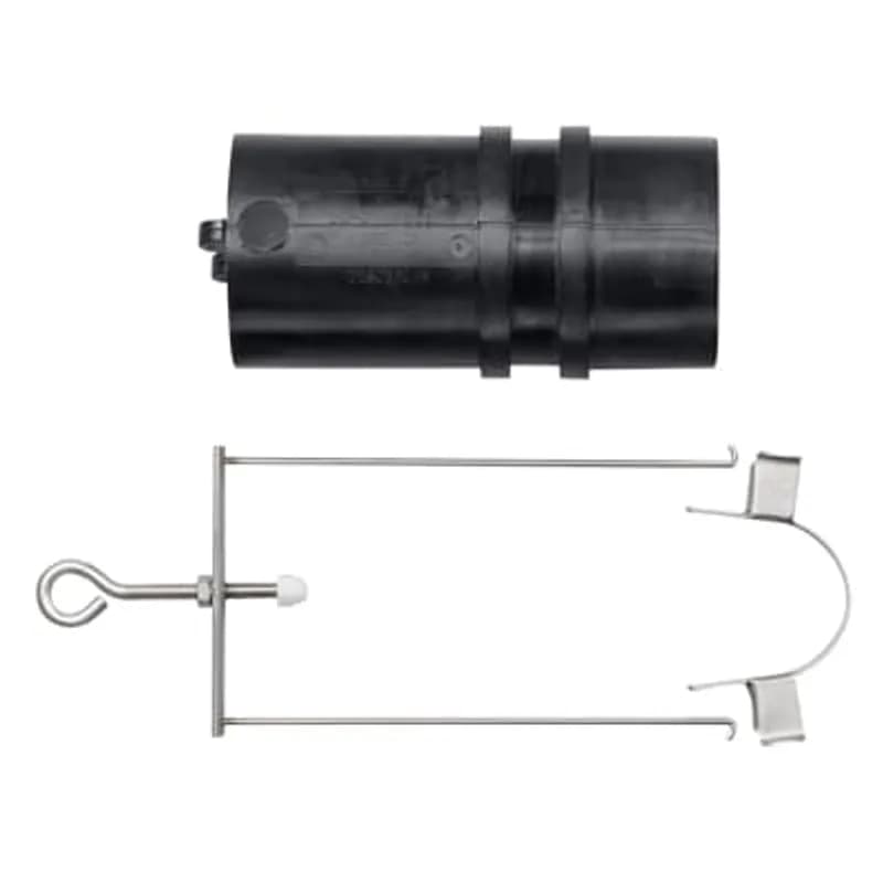
ABB Installation Products K656I-BUS 15-25kV 600 Series Deadbreak 2-Way Insulated Bus Bar with Test Point.
UPC: 783786642687
Contact for Pricing
Call +1 (262) 252-1600 (toll-free 877-268-3700) or email [email protected] for pricing and availability.
Overview
- 15-25kV voltage class with 600A continuous current rating
- 2-way deadbreak design for safe, disconnectable cable interconnections
- Integral capacitive test point for safe voltage testing without disassembly
- Fully shielded, submersible EPDM rubber construction for environmental durability
- Meets ANSI/IEEE Standard 386 with 95kV BIL (15kV) / 140kV BIL (25kV) impulse ratings
Specifications
Application | Used to joint cables in a disconnectable 2-way joint. It is suitable for small vaults and manholes due to it size compact. K656I is modular and ideal where separableComponents are required to accommodate future system circuit changes or expansions. It can also be used initially as 2-way joint with insulated caps on the un-used interface. The K656I can also be used in direct -buried applications |
Connection Type | Deadbreak |
Material | Insulated |
Material | EPDM-Rubber |
Poles | 2 |
Series | 600 Series |
Size | 3.77 inch (95.7 mm) Diameter, 9.75 inch (247.7 mm) Length of Body |
Special Features | 15kV, 600A Deadbreak rated separable connector. Compact design is suitable for small vaults and man holes. Fully shielded, fully submersible, 100 percent peroxide cured EPDM molded rubber. Reusable components reduce inventory and other costs. Includes integral capacitive test point |
Standard | ANSI/IEEE Standard 386 |
Type | 2-Way Insulated Bus Bar |
Voltage Rating | 15-25kV |
Package Dimensions (L x W x H) | 0.01 IN x 0.01 IN x 0.01 IN |
Package Dimensions (L x W x H) | 0.0254 cm x 0.0254 cm x 0.0254 cm |
Package Weight (Imperial) | 4.4500 L |
Package Weight (Metric) | 2.0190 kg |
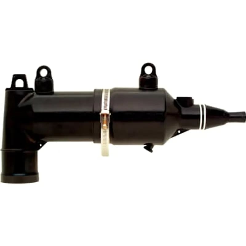
168FLR1-B5220
Molded Current Limiting Fuse Housing, Nominal Fuse Voltage Rating 8.3kV, Fuse Test Port - Two Capacitive Test Ports, Small Housing, Cable Insulation Diameter 0.635 inch - 0.905 inch / 16-23mm, Bi-Metal Conductor size 2 AWG Stranded/Compressed, 1 AWG Solid/Compact. no Sealing Kit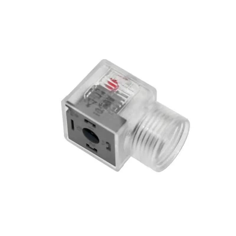
VAG-022-00
Solenoid Valve Connectors, Field Wireable, 3 Pole, Form A 18mm, 24V, 10A, LED w/MOV, .5-NPT opening

T1505063000-000
Rectangular hoods and bases portfolio features base housing, cover, hood, or hood and base housing assembly with inserts connector product types. Products are designed for bottom, side, top, or top and side cable entry. Rectangular hoods and bases offer solutions with a variety of hood and base locking device types as well as connector mounting types.
Frequently Asked Questions
What is the K656I-BUS product?
It is a 15/25kV 600A Deadbreak Separable Straight Joint with a test point, used to join cables in a disconnectable 2-way joint.
Does the K656I-BUS meet any industry standards?
Yes, the K656I-BUS meets ANSI/IEEE Standard 386, Latest Revision.
What is the impulse withstand rating for 15kV class?
For the 15kV class, the impulse withstand (BIL) is 95kV (1.2 x 50 microsecond wave).
Is the K656I-BUS submersible?
Yes, the K656I-BUS is fully shielded and fully submersible.
What components are included in the K656I-BUS kit?
Each kit contains one 2-Way Bus Bar K656I-BUS, two lubricants 82-08, and one Installation Instruction IS-0388.
Is the K656I-BUS suitable for small spaces?
Yes, its compact design makes it suitable for small vaults and manholes.
Can the K656I-BUS be used in direct-buried applications?
Yes, the K656I-BUS can be used in direct-buried applications.
What is the operating voltage for the 25kV class?
For the 25kV class, the maximum phase-to-ground operating voltage is 16.2kV, and the maximum phase-to-phase is 28kV.
What is the operating voltage for the 15kV class?
For the 15kV class, the maximum phase-to-ground operating voltage is 8.3kV, and the maximum phase-to-phase is 14.4kV.
What is the maximum continuous current rating?
The K656I-BUS has a continuous current rating of 600 Amps for both 15kV and 25kV voltage classes.
How to Install K656/K676 Series Deadbreak Receptacles
This guide provides step-by-step instructions for installing K656 and K676 series deadbreak receptacles, including cable preparation, connector crimping, and final assembly for high-voltage cable splices.
Estimated time: 2h
Tools needed:
Hex wrench (supplied), Torque wrench with 15/16” socket, Wire brush (for aluminum cable), Wire strippers, Clean rag, Approved safety solvent, 650ATY or 600RRT assembly tool
Supplies needed:
Receptacle housings, Cable adapters, I, Wye, or H Center sections, Aluminum holding collars, Lubricant (supplied or ELASTIMOLD approved), Hex-head bolts, Crimp connectors, Belleville washers, Flat washers, Nylon venting rod, No. 14 AWG copper wire (or equivalent), Tape (for markers)
- Safety First: De-energize and Inspect
Before beginning, ensure all apparatus is de-energized. Do not touch or move energized products. Inspect all parts for damage, proper rating, and compatibility with mating components. Failure to follow safety instructions can result in serious injury or death. This product should be installed only by competent personnel trained in good safety practices involving high voltage electrical equipment.
- Prepare Cable End and Initial Component Placement
Wipe the outer jacket clean for a distance of 38 inches and cut the cable end squarely. If an ECS grounding device is being used, slide the tube onto the cable for a distance of 38 inches. Then, slide the receptacle housing onto the cable for a distance of 30 inches.
- Perform Cable Preparation (Type-Specific)
Refer to the special cable preparation supplement included with these instructions (Part A for Jacketed Concentric Neutral Cable or Part B for Flat Metallic Tape Shielded Cable) to remove the cable jacket, semi-con shield, bevel the insulation, and thoroughly clean the insulation. Ensure precise measurements are followed to avoid cutting or nicking the insulation or conductor.
- Expose Conductor and Assemble Retaining Ring
Remove the protruding cable insulation by cutting it even with the end of the cable adapter, ensuring the exposed bare conductor measures 4 3/4” – 5”. Do not cut or nick the cable adapter or conductor. Assemble the aluminum retaining ring over the conductor, snugging it firmly against the cable adapter. Using the provided hex wrench, tighten the socket head screw hand tight. Confirm the exposed conductor now measures 4 3/8” to 4 3/4”.
- Prepare and Position Crimp Connector
Remove the protective cap from the crimp connector. If using aluminum cable, wire brush the conductor and immediately insert it fully into the crimp connector, which contains inhibitor. Measure the distance from the end of the connector to the holding collar; this distance must be between 6 3/4” and 7” maximum. If the distance is over 7”, do not proceed and recheck all previous work. Repeat steps 4 and 5 for any remaining cables to be joined.
- Crimp Connectors and Verify Alignment
Prior to crimping, confirm all components are positioned as shown in the instructions, ensuring the bolt holes in the crimp connectors are properly aligned with the bolt holes of the mating part. Crimp the connectors following the instructions packaged with them, rotating each crimp 90 or 180 degrees. After crimping, re-measure the distance from the end of the connector to the holding collar; if it is over 7”, do not proceed and redo all previous work.
- Assemble and Torque Bolts
Assemble the washers and bolt in the following order: flat washer against the spade contact, Belleville washer (concave side down), then the hex-head bolt. Hand tighten. Using a torque wrench with a 15/16” socket, tighten all bolts to 50 to 60 ft. lbs. The splice and cables are now in their final positions; do not attempt to move or reposition any part of the assembly after the bolts are tightened.
- Lubricate and Position Receptacle Housing
Generously apply the supplied lubricant or ELASTIMOLD approved lubricant to the outside of the cable adapter, the area of the splice section, and the inside mating surface of the receptacle housing. Slide the receptacle housing over the cable adapter and up to the edge of the interface (position shown in the documentation). Insert the nylon venting rod (supplied).
- Slide Receptacle Housing Over Splice
Attach the appropriate assembly tool (either the 650ATY or 600RRT) as shown in the instructions. Slowly operate the tool to slide the receptacle housing completely over the splice section. Remove the venting rod. WARNING: If using the 600RRT assembly tool, do not place your hand on the threaded rod or guide shaft with the tool in place. Repeat steps 8 and 9 for any remaining cables.
- Final Checks and Grounding
Check all cable adapters to make sure they are located properly and remove all vinyl tape markers. Complete the installation of the ECS grounding device according to its instructions, if applicable. Connect a short length of No. 14 AWG copper wire (or equivalent) to the grounding eyes of the housings and securely connect it to ground.
Frequently Asked Questions about ABB - Installation Products
How are Thomas and Betts products typically installed?
Thomas and Betts products are installed using a variety of methods tailored to specific applications, including the use of flexible cords and cable fittings, non-metallic cable glands, and armored cable fittings. Proper selection of fittings is crucial to match the cable type and installation environment, ensuring durability and preventing physical damage. Tools such as the Blackburn® Comfort Crimp® and HEX-FLEX® systems enhance installation efficiency and reliability, reducing labor time and ensuring secure connections.
What accessories are available for Thomas and Betts products?
Thomas and Betts offers a comprehensive range of accessories for their products, including various cord and cable fittings, non-metallic cable glands, service entrance cable fittings, and armored cable fittings. Their accessories are designed to enhance installation efficiency and ensure compatibility with different cable types and environmental conditions, providing reliable connections for a wide array of applications.
What environmental ratings do Thomas and Betts products have?
Thomas and Betts products feature robust environmental ratings, including NEMA Type 1, 2, 3, 4, 4X, 12, and 13 certifications, as well as IEC 60529 IP66 protection. These ratings ensure that their products are designed to withstand harsh industrial environments, with capabilities to resist dust, water, and corrosion, and operate effectively in a wide temperature range.
What communication protocols do Thomas and Betts products support?
Thomas and Betts products support a wide range of industrial communication protocols, including Ethernet, DeviceNet, PROFIBUS, Modbus, CANopen, and others. This extensive compatibility ensures seamless integration and reliable communication across various industrial automation systems, catering to diverse application needs.
What are the key features of Thomas and Betts products?
Thomas and Betts products are known for their innovative designs, high performance, and compliance with industry standards such as the National Electrical Code and Underwriters' Laboratories. They offer a comprehensive range of rugged and reliable electrical fittings, including liquidtight and dust-tight connections, which enhance installation efficiency and reduce overall project costs. Their products are engineered for durability in harsh environments, ensuring long-term reliability and lower installed costs.
What are the main product lines offered by Thomas and Betts?
Thomas and Betts offers a comprehensive range of product lines including electrical connectors, cable management systems, grounding and bonding solutions, and industrial automation components. Their products are designed for durability and reliability in demanding industrial environments, ensuring optimal performance and safety across various applications.
What technical support does Thomas and Betts offer?
Thomas and Betts offers comprehensive technical support, including access to field application engineers for onsite training and installation assistance. Their technical support staff is available to address inquiries related to product specifications and installation practices, ensuring optimal performance and safety of electrical systems. Additionally, they provide a variety of training programs to enhance the knowledge and skills of users in the field.
What industries and applications are Thomas and Betts products used for?
Thomas and Betts products are utilized across various industries including electrical construction, industrial automation, telecommunications, and utilities. Their extensive range of cord and cable fittings, electrical boxes, and metal framing systems are designed for applications that require durability and reliability in harsh environments, ensuring optimal performance in both permanent and temporary installations.
What certifications and standards do Thomas and Betts products comply with?
Thomas and Betts products comply with critical international certifications including UL (Underwriters Laboratories), CSA (Canadian Standards Association), and CE (European Community). Our products are designed to meet rigorous industrial standards such as NEMA enclosure ratings and IEC 60529 IP ratings, ensuring safety and reliability across various industrial applications.
What are the main product lines offered by Ocal?
Ocal offers a comprehensive range of corrosion-resistant conduit systems, including PVC-coated conduit and fittings, conduit bodies, hazardous location fittings, and strut accessories. Their products are designed to provide superior corrosion protection, featuring a hot-dipped galvanizing process and UL listed Type 4X PVC-coated conduit bodies, ensuring durability in the most demanding environments.