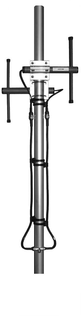
CompleTech CA160B2 bidirectional broadside - Frequency range: 154-166 MHz - Gain: 6 dBi - Polarization…
Documents & Media
Contact for Pricing
Call +1 (262) 252-1600 (toll-free 877-268-3700) or email [email protected] for pricing and availability.
Overview
- Frequency Range: 154-166 MHz
- Gain: 6 dBi
- Polarization: Vertical
- Connector: N-female / TNC-female
- VSWR: <1.5
- Radome: UV resistant ABS/FG, PU foam filling
- Radiator Material: Copper
- Mounting: 35-60 mm diameter pole
- IP Rating: 67
- Temperature Range: -40ºC - +80ºC
Specifications
Connector | N-/TNC-female |
Frequency | 154-166 MHz |
Gain | 6 dBi |
Length | 880 mm |
Mounting Diameter | Ø 35-60 |
Polarization | vertical |
Radiator Material | copper |
Radome | FG, PU foam |
VSWR | <1.5 |
Weight | 2110 g |
Wind Load | 114 N @ 150 km/h |
CA930B2
bidirectional broadside - Frequency range: 880-960 MHz - Gain: 6 dBi - Polarization: vertical - Connector: N-female - VSWR: <1.5 - Radome: ABS/FG PU foam - Radiator material: copper - Mounting: 35-60 mm diameter pole - Wind load: 50 N

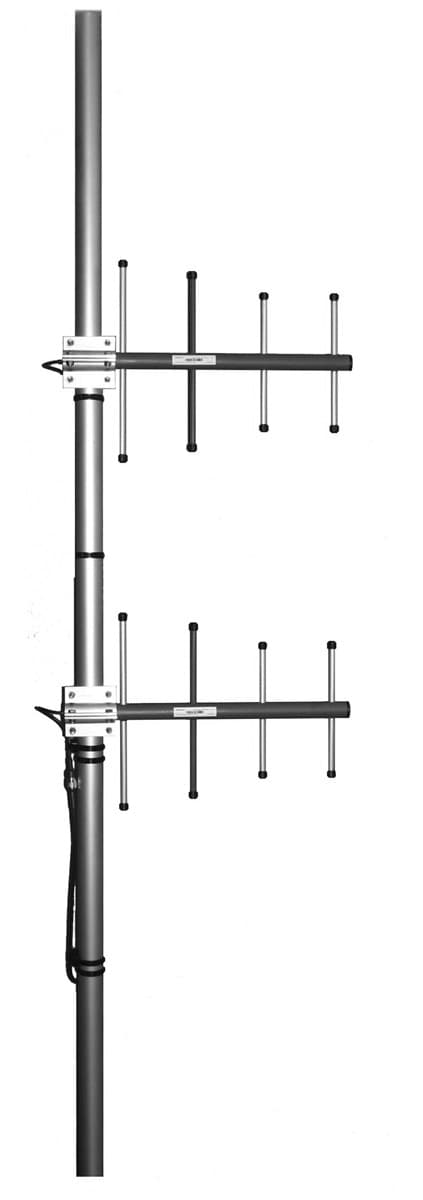
CA140S2+
directional stacked yagi array - Frequency range: 135-145 MHz - Gain: 11 dBi - Polarization: vertical/horizontal - Connector: N-/TNC-female - VSWR: <1.5 - Radome: ABS/FG PU foam - Radiator material: copper - Mounting: 35-60 mm diameter pole - Wind load: 342 N
CA230C3
offset pattern collinear - Frequency range: 221-239 MHz - Gain: 10 dBi - Polarization: vertical - Connector: N-/TNC-female - VSWR: <1.5 - Radome: ABS/FG PU foam - Radiator material: copper - Mounting: 35-60 mm diameter pole - Wind load: 135 N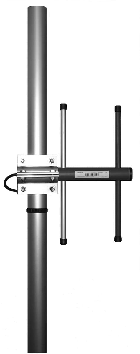
CA150Y
directional yagi - Frequency range: 144-156 MHz - Gain: 6 dBi - Polarization: vertical/horizontal - Connector: N-/ TNC-/ 7/16-female - VSWR: <1.5 - Radome: ABS/FG PU foam - Radiator material: copper - Mounting: 35-60 mm diameter pole - Wind load: 80 N
CA85B4
bidirectional stacked broadside - Frequency range: 83-88 MHz - Gain: 9 dBi - Polarization: vertical - Connector: N-/TNC-female - VSWR: <1.5 - Radome: ABS/FG PU foam - Radiator material: copper - Mounting: 35-60 mm diameter pole - Wind load: 336 N
CA150C2
offset pattern collinear - Frequency range: 144-156 MHz - Gain: 8 dBi - Polarization: vertical - Connector: N-/TNC-female - VSWR: <1.5 - Radome: ABS/FG PU foam - Radiator material: copper - Mounting: 35-60 mm diameter pole - Wind load: 120 NFrequently Asked Questions
What is the impedance of the CAB2 antenna?
The impedance of the CAB2 antenna is 50 ohm.
What is the gain of the CAB2 antenna?
The gain of the CAB2 antenna is 6 dBi.
What type of polarization does the CAB2 antenna use?
The CAB2 antenna uses vertical polarization.
What connectors are available on the CAB2 antenna?
The CAB2 antenna comes with N-female/TNC-female connectors.
What is the VSWR rating for the CAB2 antenna?
The VSWR rating for the CAB2 antenna is less than 1.5.
Does the CAB2 antenna have lightning protection?
Yes, the CAB2 antenna features DC-short circuited lightning protection.
What is the operating temperature range for the CAB2 antenna?
The CAB2 antenna can operate in temperatures ranging from -40ºC to +80ºC.
What is the IP rating of the CAB2 antenna?
The CAB2 antenna has an IP rating of 67.
What frequencies does the CAB2 antenna support?
The CAB2 antenna supports multiple frequency bands including 83-88 MHz, 135-145 MHz, 144-159 MHz, 154-166 MHz, 163-177 MHz, 221-239 MHz, 326-353 MHz, 336-364 MHz, 365-395 MHz, 380-410 MHz, 405-440 MHz, 440-475 MHz, 830-890 MHz, and 880-960 MHz.
What materials are used for the radome and radiator of the CAB2 antenna?
The radome is made of UV resistant ABS/FG with PU foam filling, and the radiator is made of copper.
How to Install the CA160B2 Controller
Step-by-step guide for installing and configuring the CA160B2 Controller for optimal performance.
Estimated time: 45m
Tools needed:
Screwdriver, Wire strippers, Multimeter
Supplies needed:
Mounting screws, Terminal connectors, Self-amalgamating tape
- Mount the controller
Secure the CA160B2 controller to the designated mounting surface using the provided mounting screws. Ensure it is level and firmly attached.
- Connect the wiring
Strip the ends of the wires and connect them to the appropriate terminals on the CA160B2 controller. Use terminal connectors to ensure a secure connection.
- Seal the connections
Cover all connectors and cable junctions with self-amalgamating tape to provide weather protection and prevent moisture ingress.
- Verify the installation
Use a multimeter to check the voltage and continuity of the connections to ensure everything is functioning correctly.