
Contact for Pricing
Overview
- Nominal Voltage: 27 kV
- Withstand Current: 20 kA (SYM)
- Continuous Current: 600 Amps
- Handle Position: Right
- Electrical Interlock: DC
Specifications
Amperage Rating | 600 A |
Application | 20kA Rated with 600 Amp Interface |
Operating Temperature | -40 to +65 C |
Size | Height to center of Bushing 33-1/2 in |
Special Features | Construction Submersible, Corrosion Resistant, Fully Shielded, Red Colored Indicator Showing Closed Position |
Standard | IEEE C37.74 , IEEE 386 |
Type | Tru-Break Module |
Voltage Rating | 27 kV |
Package Dimensions (L x W x H) | 0.01 IN x 0.01 IN x 0.01 IN |
Package Dimensions (L x W x H) | 0.0254 cm x 0.0254 cm x 0.0254 cm |
Package Weight (Imperial) | 1.0000 L |
Package Weight (Metric) | 0.4540 kg |
TB27-20-6-R-I-N-S
Tru-Break Interlock Linkage Kit for MVI, Nominal Voltage: 27kV, Withstand Current: 20kA (SYM), Continuous Current: 600 Amps, Handle Position: Right, Mating Device: MVI3, Electrical Interlock : None, Spanish Labels and Instructions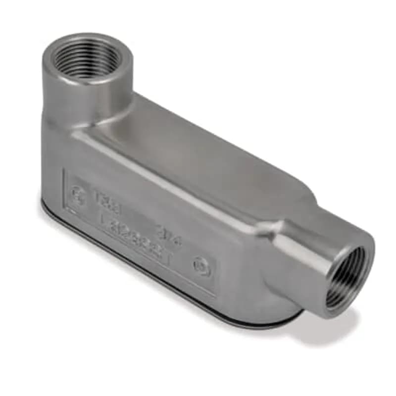
LB28SST-TB
3/4 Inch 316 Stainless Steel Form 8 (LB) Conduit Body, Gasket and Cover with Polished Finish

Frequently Asked Questions
What are the voltage and current ratings?
The Tru-Break module is rated for 15–29.3 kV, 800 A continuous load current, and 20 kA short circuit withstand current systems.
What type of connection does it use?
It uses an IEEE 386 600-amp interface bolted connection.
Is the module hot-stick operable?
Yes, the Tru-Break module is hot-stick operable.
Does it allow visual verification of contact status?
Yes, it has clear viewing windows for easy visual verification of contact status.
What is its basic insulation level (BIL)?
It is capable of withstanding a full 125 kV basic insulation level (BIL) impulse voltage.
Can the module be used in harsh environments?
Yes, it is submersible and storm-hardened, designed for harsh vault and pad-mount environments.
Is the Tru-Break module retrofittable?
Yes, retrofittable options are available for existing Elastimold three-phase and single-phase MVS switches or MVI interrupters.
What standard is the module tested to?
The Tru-Break module is tested to the IEEE C37.74-2014 standard.
How do I confirm retrofittability for my system?
Contact your ABB representative to confirm if your specific configuration is retrofittable.
What is the size of the viewing windows?
The viewing windows are 1.75 inches and have hotstick-removable caps for cleaning.
How to Install the Elastimold® Tru-Break™ Retrofit Module (TB27-20-6-R-S-DC)
Complete installation guide for mounting and wiring the Elastimold® Tru-Break™ Retrofit Module (TB27-20-6-R-S-DC) onto MVS switchgear with a motor operator. This guide covers handle, grounding, module mounting, and interlock setup.
Estimated time: 2h
Tools needed:
Lifting eye bolts (customer supplied, 1/2-13UNC, min shank 2.5"), Torque wrench (for 16-18 Ft-Lbs, 50-60 Ft-Lbs, 50-75 In-Lbs, 75-85 In-Lbs), Wrenches/sockets (for 1/4-20, 1/4-28, 5/8-11 bolts/nuts, 1/2" clevis pins)
Supplies needed:
Elastimold Tru-Break Module (Three Phase), 3' Electronic Lockout Cable, 6 AWG Braided Ground Cable, MVS Linkage Bar, 1/2" Diameter, 3/4" Long Clevis Pin (x2), Locking Cotter Pin (x2), Mounting Clips (x2), 1/4-20 Nylon Insert Locknut (x2), 1/4-28 Hex Head Bolt (x2), Switchgear Operating Handle for Tru-Break, Basic Insulating Plug with Cap (x3), 5/8-11 x 2 3/4" Length Stud (x3), Silicone Grease Packets (x9), Spacer (for MVS handle installation), Belleville washer (for MVS handle installation), Original MVS handle bolt (retained from switchgear)
- Perform Pre-Installation Checks and Safety Procedures
DANGER: All apparatus must be de-energized during installation or removal of parts. Do not touch or move energized products. This product should be installed only by competent personnel trained in good safety practices involving high voltage electrical equipment. Inspect all parts for damage, proper rating, and compatibility with mating parts. Check the contents of the package to ensure they are complete and undamaged. Read the entire installation instructions before starting and have all required tools at hand, maintaining cleanliness throughout the procedure.
- Lift and Handle the Tru-Break Module
Screw customer-supplied 1/2-13UNC lifting eye bolts (minimum shank length 2.5 inches or longer) into the lifting provisions of the Tru-Break module. An additional lifting strap can also be used in the designated area (refer to Figure 1 in the document). Ensure the strap is taut and free from slack before lifting. Carefully lift the unit and remove it from its crate.
- Prepare Switchgear and Install New Operating Handle
Prepare the switchgear by ensuring it is in the open position. Remove any cable accessories from the 600A interfaces. Remove the original switchgear handle, retaining the bolt for MVS applications for future use. Discard the original MVS handle and its position indicator. Install the provided Tru-Break switchgear operating handle. For MVS, install the spacer in place of the position indicator and ensure the Belleville washer is correctly oriented. Torque the MVS handle bolt to 16-18 Ft-Lbs.
- Install Tru-Break Ground Cable to Switchgear
Loosen the ground lug on the existing switchgear. Insert the provided 6 AWG braided ground cable into the switchgear ground lug. Tighten the switchgear ground lug securely.
- Mount the Tru-Break Module to Switchgear
Thread the three provided 5/8-11 x 2 3/4" length studs into the switchgear interfaces about 3 turns to aid in mounting the Tru-Break. Clean the switchgear interfaces and apply the provided silicone grease to both the switchgear interfaces and the female interfaces of the Tru-Break. Do not substitute silicone grease. Lift the Tru-Break module and carefully install it onto the switchgear in the orientation shown in Figure 12 of the document.
- Install Basic Insulating Plugs (BIPs)
Install the three Basic Insulating Plugs (BIPs) by hand into the Tru-Break module. Using a torque wrench, torque each BIP to 50-60 Ft-Lbs. Install the voltage detection caps onto the BIPs. Refer to the BIP instruction sheet for further details if needed.
- Connect Tru-Break Ground Cable to Module
Feed the previously installed ground cable through the Tru-Break mainbodies as shown in Figure 13 of the document. Insert the cable into the ground lug on the Tru-Break module. Tighten the Tru-Break ground lug securely.
- Install Mounting Clip Kit
Place the "U"-shaped part of a mounting clip over the flange of the switchgear cover. Slide the clip down onto the Tru-Break cover bolt. Torque the 1/4-20 nylon insert locknuts to 50-75 In-Lbs. Install the 1/4-28 bolts where shown (Figures 14-16) and torque them to 75-85 In-Lbs. Repeat this process for the second mounting clip.
- Install Interlock Linkage Kit (for MVS)
Rotate the Tru-Break interlock lever towards the front of the cover. Install the provided MVS linkage kit, which includes the Linkage Bar for MVS, two 1/2" Diameter, 3/4" Long Clevis Pins, and two Locking Cotter Pins, as depicted in Figures 17 and 18 of the document. Ensure the counterbore on the linkage bar allows the pin head to sit flush with the bar.
- Connect Motor Operator Cables
Remove the 12-pin cable from the motor box of the mating switchgear. Install this 12-pin cable onto the Tru-Break's 12-pin female receptacle. Install the provided 3-foot electronic lockout cable from the Tru-Break's male receptacle to the motor box receptacle on the switchgear (refer to Figures 21 and 22).
- Reinstall Motor Linkage
Reinstall the motor linkage to the newly installed switchgear handle as shown in Figures 23 and 24 of the document. Pay close attention to the orientation of the welded boss on the linkage and ensure the lanyard loop is positioned between the washer and the linkage.
- Reinstall Cable Accessories
Reinstall any cable accessories that were previously installed on the switchgear to the Tru-Break interfaces.
- Test Interlock Operation (Manual)
Verify the interlock system is functioning correctly. While the switchgear is in the open position, confirm the Tru-Break handle is operable between the open and closed positions. Move the Tru-Break to the open position and verify the switchgear handle cannot be placed into the closed position. Move the Tru-Break to the closed position, then move the switchgear to the closed position. Verify the Tru-Break handle cannot now move to the open position.
- Test Interlock Operation (With Motor Operator)
Test the interlock system with the motor operator. While the switchgear is in the open position, confirm the Tru-Break handle is operable between the open and closed positions. Move the Tru-Break to the open position and verify the motor operator does not move the MVS or MVI motor due to the electrical interlock. Note: If using an Elastimold® motor operator control, the open and closed lights will flash continuously and must be reset by powering down the control. Move the Tru-Break to the closed position. Move the switchgear to the closed position using the motor operator. Verify the Tru-Break handle cannot move to the open position.
Frequently Asked Questions about ABB - Installation Products
How are Thomas and Betts products typically installed?
Thomas and Betts products are installed using a variety of methods tailored to specific applications, including the use of flexible cords and cable fittings, non-metallic cable glands, and armored cable fittings. Proper selection of fittings is crucial to match the cable type and installation environment, ensuring durability and preventing physical damage. Tools such as the Blackburn® Comfort Crimp® and HEX-FLEX® systems enhance installation efficiency and reliability, reducing labor time and ensuring secure connections.
What accessories are available for Thomas and Betts products?
Thomas and Betts offers a comprehensive range of accessories for their products, including various cord and cable fittings, non-metallic cable glands, service entrance cable fittings, and armored cable fittings. Their accessories are designed to enhance installation efficiency and ensure compatibility with different cable types and environmental conditions, providing reliable connections for a wide array of applications.
What environmental ratings do Thomas and Betts products have?
Thomas and Betts products feature robust environmental ratings, including NEMA Type 1, 2, 3, 4, 4X, 12, and 13 certifications, as well as IEC 60529 IP66 protection. These ratings ensure that their products are designed to withstand harsh industrial environments, with capabilities to resist dust, water, and corrosion, and operate effectively in a wide temperature range.
What communication protocols do Thomas and Betts products support?
Thomas and Betts products support a wide range of industrial communication protocols, including Ethernet, DeviceNet, PROFIBUS, Modbus, CANopen, and others. This extensive compatibility ensures seamless integration and reliable communication across various industrial automation systems, catering to diverse application needs.
What are the key features of Thomas and Betts products?
Thomas and Betts products are known for their innovative designs, high performance, and compliance with industry standards such as the National Electrical Code and Underwriters' Laboratories. They offer a comprehensive range of rugged and reliable electrical fittings, including liquidtight and dust-tight connections, which enhance installation efficiency and reduce overall project costs. Their products are engineered for durability in harsh environments, ensuring long-term reliability and lower installed costs.
What are the main product lines offered by Thomas and Betts?
Thomas and Betts offers a comprehensive range of product lines including electrical connectors, cable management systems, grounding and bonding solutions, and industrial automation components. Their products are designed for durability and reliability in demanding industrial environments, ensuring optimal performance and safety across various applications.
What technical support does Thomas and Betts offer?
Thomas and Betts offers comprehensive technical support, including access to field application engineers for onsite training and installation assistance. Their technical support staff is available to address inquiries related to product specifications and installation practices, ensuring optimal performance and safety of electrical systems. Additionally, they provide a variety of training programs to enhance the knowledge and skills of users in the field.
What industries and applications are Thomas and Betts products used for?
Thomas and Betts products are utilized across various industries including electrical construction, industrial automation, telecommunications, and utilities. Their extensive range of cord and cable fittings, electrical boxes, and metal framing systems are designed for applications that require durability and reliability in harsh environments, ensuring optimal performance in both permanent and temporary installations.
What certifications and standards do Thomas and Betts products comply with?
Thomas and Betts products comply with critical international certifications including UL (Underwriters Laboratories), CSA (Canadian Standards Association), and CE (European Community). Our products are designed to meet rigorous industrial standards such as NEMA enclosure ratings and IEC 60529 IP ratings, ensuring safety and reliability across various industrial applications.
What are the main product lines offered by Ocal?
Ocal offers a comprehensive range of corrosion-resistant conduit systems, including PVC-coated conduit and fittings, conduit bodies, hazardous location fittings, and strut accessories. Their products are designed to provide superior corrosion protection, featuring a hot-dipped galvanizing process and UL listed Type 4X PVC-coated conduit bodies, ensuring durability in the most demanding environments.