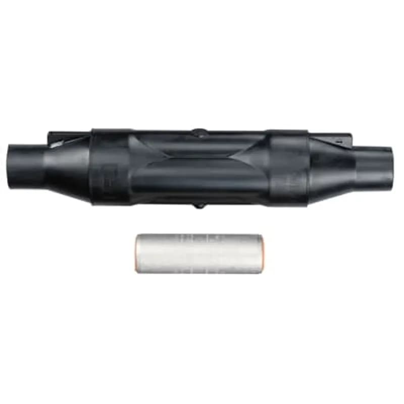
ABB Installation Products 35PCJ1K 35kV Power Cable Joint Style 1 with Single Piece Housing, Cable Insulation Diameter…
UPC: 783786318421
Contact for Pricing
Call +1 (262) 252-1600 (toll-free 877-268-3700) or email [email protected] for pricing and availability.
Overview
- 35 kV Voltage Rating
- Single Piece Housing Design
- Accommodates Cable Insulation Diameter: 1.090" to 1.310"
- ABB Installation Products Manufacturer
- Style 1 Cable Joint
Specifications
Application | For Direct Burial, Vault, Submersible and Other Severe Service Applications |
Color | Black |
Connection | Compression |
Insulation | Yes |
Material | EPDM Rubber |
Number Of Conductors | 2 |
Size | 14-3/8 inch long |
Special Features | Power Cable Joints utilize permanently crimped connectors. PCJ housings are fully insulated, shielded and sealed for direct-burial, vault, submersible and other servere service applications. Units have been designed and tested per IEEE Standard 404 to ensure system matched performance and ratings equal to the cable to which the splice will be installed. Power Cable Joints are available in two styles. Style 1 uses a single-piece housing that is sized to accommodate a specific range of cable - ideally suited to straight splicing of the same or similar cable. Style 2 designs incorporate a universal housing with separate cable adapters to allow transition splices of different types and sizes of cable |
Standard | IEEE Standard 404 |
Type | Power Cable Joint |
Voltage Rating | 35 kV |
Package Dimensions (L x W x H) | 0.01 IN x 0.01 IN x 0.01 IN |
Package Dimensions (L x W x H) | 0.0254 cm x 0.0254 cm x 0.0254 cm |
Package Weight (Imperial) | 2.5000 L |
Package Weight (Metric) | 1.1340 kg |
35PCJ1-H
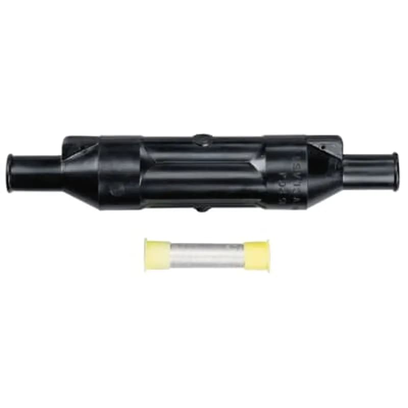
35kV, PCJ - Power Cable Joint, with Single Piece Housing, Cable Insulation Diameter .850 - 1.050 inches, Housing Only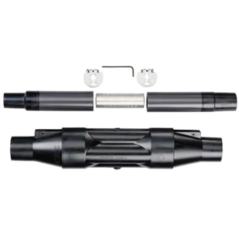
15PCJ2N1410-P1380
15kV Power Cable Joint Style 2 with Universal Housing and Separate Cable Adapters. Cable Insulation Diameter 1.515 inch to 1.780 inch. Aluminum Conductor. Conductor Size AWG Stranded 1000. Cable Insulation Diameter 1.725 inch to 1.935 inch. Aluminum Conductor. Conductor Size AWG Stranded 750.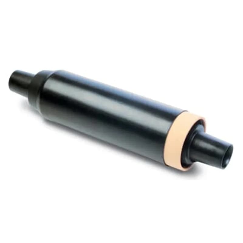
69TCJS1R242PVDNNB
69 kv, Transmission Cable Joint, Housing Type - Shieldbreak, Housing Style 1, Housing Size R Bore Diameter at Jacket/Insulation Transition 1.930. Connector Type - Copper, Connector Code 42P - Conductor Diameter Range - 1.146-1.220 inch (29.11-30.99mm), Heatsink Bore - V - 2.046 inch Diameter. Type Shield - D - Copper Tape and Neutral Wire, Metallic Screen Continuity Kit - N - not required, Armor Kit - N - not required, Outer Jacket Restoration Kit - B - Heat Shrink25PCJ1H1240-1220
25kV Power Cable Joint Style 1 with Single Piece Housing, Cable Insulation Diameter 0.850 inch to 1.050 inch. Aluminum Conductor. Conductor Size AWG Stranded 1/0 /Solid 2/0. Aluminum Conductor. Conductor Size AWG Stranded #2/Solid #1.15PCJ2L1380-L1330
15kV Power Cable Joint Style 2 with Universal Housing and Separate Cable Adapters. Cable Insulation Diameter 1.180 inch to 1.465 inch. Aluminum Conductor. Conductor Size AWG Stranded 750. Cable Insulation Diameter 1.180 inch to 1.465 inch. Aluminum Conductor. Conductor Size AWG Stranded 500.35PCJ1K1260-S
35kV Power Cable Joint Style 1, Cable Insulation Diameter 1.090 inch to 1.310 inch. Aluminum Compression Lug. Conductor Size AWG or kcmil, Compressed Stranded 3/0 /Compacted Solid 4/0 /mmSquared Compact 95. Cold Shrinkable Jacket Seal included.15PCJ1G2270
15kV Power Cable Joint Style 1 with Single Piece Housing, Cable Insulation Diameter 0.760 inch to 0.950 inch. Copper Conductor. Conductor Size AWG Stranded 4/0 /Solid 250.15PCJ1M1410Z
15kV Power Cable Joint Style 1 with Single Piece Housing, Cable Insulation Diameter 1.370 inch to 1.630 inch. Aluminum Conductor. Conductor Size AWG Stranded 1000. Tin, Thin Walled, ConnectorFrequently Asked Questions
What voltage classes are PCJ power cable joints available in?
PCJ power cable joints are available in 15 kV, 25 kV, and 35 kV classes.
What types of conductors are compatible with PCJ cable joints?
PCJ power cable joints are compatible with copper or aluminum conductors, supporting a wide range of sizes up to 1250 kcmil.
Where can Elastimold PCJ power cable joints be installed?
They can be installed in direct-burial, underground vault, and overhead applications, providing a permanent, fully shielded, fully submersible splice.
What is the continuous current rating for PCJ cable joints?
The continuous current rating for PCJ power cable joints is equal to that of the cable rating.
What is the short-time current rating for PCJ cable joints?
The short-time current rating for PCJ power cable joints is equal to that of the cable rating, up to 35 kA.
Which connector type is used for copper cable splicing?
Kits include a copper compression connector suitable for splicing copper conductors to copper conductors only.
Can copper connectors be used with aluminum conductors?
No, copper connectors should not be used on aluminum conductors.
What is the insulation diameter range for 35PCJ1K?
For 35PCJ1K, the cable insulation diameter range is 1.090 inches minimum to 1.310 inches maximum.
What is the overall length of the 35PCJ1K joint?
The overall length (Dimension A) for the 35PCJ1KX is 14 3/8 inches.
Which connector type is used for aluminum cable splicing?
Kits include an aluminum compression connector suitable for splicing aluminum to aluminum or aluminum to copper conductors.
How to Install the 25PCJ1 Series Straight Joint
This guide provides detailed instructions for installing the 15/25/35PCJ1 Series straight joint, a permanent, fully shielded, and submersible joint for wire shielded cables. It covers cable preparation, splice installation, and final assembly for aluminum to aluminum or aluminum to copper conductors.
Estimated time: 2h
Tools needed:
Wire brush, Crimping tool (for splice and connectors), T&B WT3D tool (recommended for 35kV cable ties, if applicable), Cable stripping tools, Utility knife
Supplies needed:
Joint Housing, Splice (Conductor Contact), Lubricant (DO NOT SUBSTITUTE), Appropriate connector (for grounding wires), DELTECt Cable ties (TYD5135, for 35kV only), No. 14 AWG copper wire (or equivalent, if shield wires are smaller)
- Ensure Safety and Prepare for Installation
DANGER: All apparatus must be de-energized during installation. Do not touch or move energized products. This product should be installed only by competent personnel trained in good safety practices involving high voltage electrical equipment. Inspect all parts for damage, rating, and compatibility with mating parts. Gather all required tools and supplies, and maintain cleanliness throughout the procedure.
- Prepare Cables for Joint Centerline
Overlap both cables and cut them to 12 inches (305mm) from the intended centerline of the joint to ensure sufficient length of shield wires. Where applicable, remove the cable jacket of Cable 1 to 37 inches (940mm) and Cable 2 to 21 inches (530mm). Fold back the shield wires. Finally, cut both cables at the joint centerline.
- Prepare Cable 1 and Store Housing
Taper the edge of Cable 1's insulation shield at least 1/2 inch (13mm) to no greater than 1-1/2 inches (38mm). Clean and lubricate the insulation shield. Lubricate the inside bore of the joint housing on both ends. Slide the housing onto Cable 1, positioning it up to the shield wires.
- Prepare Cables for Splice Installation
Carefully remove the cable insulation and then the insulation shield from both cables. DO NOT CUT OR NICK THE CABLE INSULATION OR CONDUCTOR during this process. Refer to the provided dimensions for 'X' and 'Y' based on your conductor size (e.g., 500-750 MCM or 1000 MCM).
- Install the Splice
If conductors are aluminum, wire-brush them thoroughly and immediately insert them into the splice. Check the dimension against the 'Max Check Before' table; if it exceeds, redo the assembly. Crimp the splice following the manufacturer's recommendations. Wipe off any excess inhibitor. Check the distance between cable insulations against the 'Max Check After' table; if it exceeds, redo the assembly. Remove any sharp protrusions or burrs generated during crimping and ensure all metal chips/filings are removed from the splice and joint assembly area. Clean the cables where indicated and lubricate in the direction of the arrows to create a build-up or ramp of lubricant at the edge of the insulation shield.
- Complete Joint Assembly
Slide the housing into its final position, ensuring proper placement by observing and equalizing the deformation of the joint ends caused by the underlying cable insulation shield. For 35kV ONLY: Install two DELTECt Cable ties on each end of the cable entrance, starting 1/4 inch (6mm) from the splice edge, then a second 1/4 inch (6mm) from the first with offset locking heads (T&B WT3D tool recommended). Remove and discard the yellow pin from the joint grounding eye. Retrain the shield wires and secure them to the ends of the joint. Insert one shield wire from Cable 1 (if #14 AWG or larger) through the joint grounding eye, and repeat for Cable 2 (use separate #14 AWG copper wire if shield wires are smaller). Connect the joint grounding wires and remaining shield wires using an appropriate connector. Finally, reconstruct the cable jacket (where applicable) over both cables and the joint housing.
Frequently Asked Questions about ABB - Installation Products
How are Thomas and Betts products typically installed?
Thomas and Betts products are installed using a variety of methods tailored to specific applications, including the use of flexible cords and cable fittings, non-metallic cable glands, and armored cable fittings. Proper selection of fittings is crucial to match the cable type and installation environment, ensuring durability and preventing physical damage. Tools such as the Blackburn® Comfort Crimp® and HEX-FLEX® systems enhance installation efficiency and reliability, reducing labor time and ensuring secure connections.
What accessories are available for Thomas and Betts products?
Thomas and Betts offers a comprehensive range of accessories for their products, including various cord and cable fittings, non-metallic cable glands, service entrance cable fittings, and armored cable fittings. Their accessories are designed to enhance installation efficiency and ensure compatibility with different cable types and environmental conditions, providing reliable connections for a wide array of applications.
What environmental ratings do Thomas and Betts products have?
Thomas and Betts products feature robust environmental ratings, including NEMA Type 1, 2, 3, 4, 4X, 12, and 13 certifications, as well as IEC 60529 IP66 protection. These ratings ensure that their products are designed to withstand harsh industrial environments, with capabilities to resist dust, water, and corrosion, and operate effectively in a wide temperature range.
What communication protocols do Thomas and Betts products support?
Thomas and Betts products support a wide range of industrial communication protocols, including Ethernet, DeviceNet, PROFIBUS, Modbus, CANopen, and others. This extensive compatibility ensures seamless integration and reliable communication across various industrial automation systems, catering to diverse application needs.
What are the key features of Thomas and Betts products?
Thomas and Betts products are known for their innovative designs, high performance, and compliance with industry standards such as the National Electrical Code and Underwriters' Laboratories. They offer a comprehensive range of rugged and reliable electrical fittings, including liquidtight and dust-tight connections, which enhance installation efficiency and reduce overall project costs. Their products are engineered for durability in harsh environments, ensuring long-term reliability and lower installed costs.
What are the main product lines offered by Thomas and Betts?
Thomas and Betts offers a comprehensive range of product lines including electrical connectors, cable management systems, grounding and bonding solutions, and industrial automation components. Their products are designed for durability and reliability in demanding industrial environments, ensuring optimal performance and safety across various applications.
What technical support does Thomas and Betts offer?
Thomas and Betts offers comprehensive technical support, including access to field application engineers for onsite training and installation assistance. Their technical support staff is available to address inquiries related to product specifications and installation practices, ensuring optimal performance and safety of electrical systems. Additionally, they provide a variety of training programs to enhance the knowledge and skills of users in the field.
What industries and applications are Thomas and Betts products used for?
Thomas and Betts products are utilized across various industries including electrical construction, industrial automation, telecommunications, and utilities. Their extensive range of cord and cable fittings, electrical boxes, and metal framing systems are designed for applications that require durability and reliability in harsh environments, ensuring optimal performance in both permanent and temporary installations.
What certifications and standards do Thomas and Betts products comply with?
Thomas and Betts products comply with critical international certifications including UL (Underwriters Laboratories), CSA (Canadian Standards Association), and CE (European Community). Our products are designed to meet rigorous industrial standards such as NEMA enclosure ratings and IEC 60529 IP ratings, ensuring safety and reliability across various industrial applications.
What are the main product lines offered by Ocal?
Ocal offers a comprehensive range of corrosion-resistant conduit systems, including PVC-coated conduit and fittings, conduit bodies, hazardous location fittings, and strut accessories. Their products are designed to provide superior corrosion protection, featuring a hot-dipped galvanizing process and UL listed Type 4X PVC-coated conduit bodies, ensuring durability in the most demanding environments.