Choosing and Implementing Efficient Motor Drivers and Controllers for DC and Brushless Motors
2026-03-15
· Gross Automation
· 6 min read
Choosing and Implementing Efficient Motor Drivers and Controllers for DC and Brushless Motors
Efficient motor control is critical in industrial automation to ensure reliability, protect equipment, and optimize performance. Yet, engineers often face challenges such as accurately sensing motor current for stall detection, isolating control signals from high-power circuits, and fine-tuning brushless DC (BLDC) motor timing. This article provides practical guidance on selecting and implementing motor drivers and controllers, focusing on current sensing, MOSFET driving with optocouplers, BLDC timing strategies, and compact controller design with isolation. We also reference proven products from ABB, WEG, LS Electric, and others available through Gross Automation.
Accurate Current Sensing for DC Motor Stall Detection
Why Current Sensing Matters
Stall detection protects motors from damage caused by overload or mechanical blockage. When a DC motor stalls, the current spikes sharply, which, if detected promptly, allows the control system to shut down or reduce power to prevent overheating and failure.
How to Sense Motor Current Effectively
-
Use a Low-Resistance Shunt Resistor:
Place a precision low-ohm resistor in series with the motor supply line. The voltage drop across the resistor is proportional to the motor current. For example, Littelfuse’s 1SVR405510R3070 shunt resistor offers reliable current measurement with minimal power loss. -
Amplify and Condition the Signal:
The voltage across the shunt is typically small and requires amplification. Use differential amplifiers or dedicated current-sense amplifiers to boost the signal while filtering noise. -
Isolate the Measurement Circuit:
To protect sensitive electronics and avoid ground loops, isolate the current sensing signal. Optocouplers such as ABB’s 1344101000 provide galvanic isolation between the high-power motor circuit and the control electronics. -
Implement Real-Time Monitoring:
Feed the conditioned and isolated current signal into a microcontroller or PLC analog input for continuous monitoring. Set thresholds to detect stall conditions and trigger protective actions.
Practical Tip
When selecting shunt resistors and amplifiers, consider the motor’s nominal current and stall current to size components appropriately. Oversizing reduces sensitivity; undersizing risks component damage.
Driving MOSFETs with Optocouplers for Safe and Reliable Switching
The Challenge of Driving High-Power MOSFETs
MOSFETs are widely used for motor control due to their fast switching and efficiency. However, the gate drive signals often need to be isolated from the control logic to prevent noise and voltage spikes from damaging the controller.
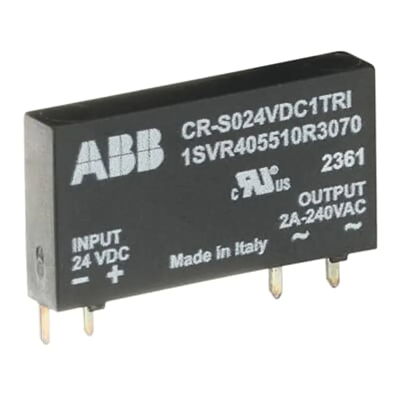
Best Practices for MOSFET Gate Driving Using Optocouplers
-
Choose High-Speed Optocouplers:
Use optocouplers designed for fast switching to avoid delays that reduce PWM control quality. ABB’s 1341011700 optocoupler offers high-speed performance suitable for MOSFET gate drive isolation. -
Implement Proper Gate Drive Circuits:
After the optocoupler, use a dedicated gate driver IC or a transistor stage to provide sufficient current to charge and discharge the MOSFET gate quickly, minimizing switching losses. -
Maintain Signal Integrity:
Use twisted pair wiring and proper PCB layout to reduce electromagnetic interference (EMI). Place the optocoupler close to the MOSFET to minimize lead length. -
Ensure Adequate Isolation Voltage:
Verify that the optocoupler’s isolation voltage rating exceeds the maximum expected voltage in the motor drive circuit. For example, ABB’s optocouplers typically support isolation voltages above 5 kV.
Step-by-Step MOSFET Drive Setup
- Connect the control signal output from the microcontroller to the LED input side of the optocoupler.
- On the output side, connect the phototransistor to the gate driver circuit.
- Use a pull-up resistor and a gate driver transistor or IC to supply the required gate charge.
- Test switching speed and verify isolation effectiveness before integrating into the motor controller.
Understanding Non-Zero Timing in Brushless DC Motor Control
What is Non-Zero Timing?
In BLDC motors, electronic commutation replaces brushes by switching current through stator windings in a sequence synchronized to rotor position. Non-zero timing means advancing or retarding the commutation switching relative to the rotor position to optimize performance.
Why Use Non-Zero Timing?
-
Improve Torque and Efficiency:
Advancing the commutation timing slightly (positive advance) can increase torque output and efficiency at higher speeds. -
Reduce Noise and Vibration:
Proper timing reduces torque ripple, resulting in smoother motor operation. -
Compensate for Back-EMF and Load Variations:
Adjusting timing helps maintain optimal current flow despite changes in motor speed or load.
How to Implement Non-Zero Timing
- Use sensors such as Hall effect sensors or encoders to detect rotor position accurately.
- Employ a motor controller capable of adjusting commutation timing dynamically.
- Start with zero timing at low speeds, then gradually advance timing as speed increases.
- Monitor motor current and temperature to avoid overstressing the motor.
Troubleshooting Common Timing Issues
-
Excessive Heat or Noise:
May indicate too much timing advance. Reduce advance angle. -
Reduced Torque or Stalling:
May indicate insufficient timing advance or sensor misalignment. -
Irregular Speed Response:
Check sensor signals and wiring for noise or faults.
Designing Compact Motor Controllers with Isolation
Benefits of Integrated, Isolated Controllers
Compact motor controllers reduce panel space, simplify wiring, and improve reliability. Isolation between control and power circuits protects sensitive electronics and personnel.
Key Design Considerations
-
Use Integrated Motor Controllers:
LS Electric and WEG offer compact motor controllers that integrate power electronics, current sensing, and control logic in a single unit. -
Incorporate Optocouplers for Signal Isolation:
As discussed, optocouplers like ABB’s 1338018000 provide galvanic isolation for control signals. -
Select Modular Components:
Modular components such as Littelfuse’s 1SVR405510R3050 shunt resistors and ABB’s 1393002500 MOSFET modules simplify assembly and maintenance. -
Optimize PCB Layout:
Separate high-power and low-power sections, use ground planes, and place isolation barriers to minimize EMI. -
Include Diagnostic Features:
Integrated current sensing and fault detection enable real-time monitoring and preventive maintenance.
Example Compact Controller Setup
- Power stage using ABB MOSFET modules for efficient switching.
- Current sensing with Littelfuse shunt resistors and isolated amplifiers.
- Control logic implemented on a microcontroller or PLC with isolated inputs/outputs.
- Optocoupler-based isolation between control and power circuits.
- Enclosure designed for thermal management and easy access.
Conclusion: Leveraging Gross Automation for Motor Control Solutions
Selecting and implementing efficient motor drivers and controllers requires careful attention to current sensing, MOSFET driving techniques, BLDC timing, and isolation. By using high-quality components from trusted manufacturers like ABB, WEG, LS Electric, and Littelfuse, you can build reliable, efficient motor control systems that protect equipment and optimize performance.
Gross Automation is your go-to source for these critical components and expert technical support. Contact us today to discuss your motor control application and find the right products to meet your needs.
Quick Answers from Products
What is the maximum bundle diameter this tie can secure?
The MLT8WH-LP316 can secure bundles up to 8.0 inches (203mm) in diameter.
From: MLT8WH-LP316 by PanduitWhat is the operating voltage for the ABB CR-S024VDC1TRA?
The ABB CR-S024VDC1TRA optocoupler is designed for a 24V DC input.
From: 1SVR405510R3050 by ABB - ElectrificationWhat is the rated control supply voltage for this optocoupler?
The rated control supply voltage for the CRS pluggable optocoupler is 24V DC.
From: 1SVR405510R3070 by ABB - ElectrificationRelated Articles
Emerging Trends and Innovations in Industrial Automation: AGVs, Energy Analyzers, and Microgrid Breakers
6 min readEmerging Trends and Competitive Strategies in Factory and Logistics Automation
4 min readWhen Does It Make Sense for SMBs to Automate? Evaluating ROI from PLCs to Full DCS and SCADA Systems
10 min readNavigating Obsolescence: Upgrading Legacy GE Surge Protective Devices Before 2026
6 min read