
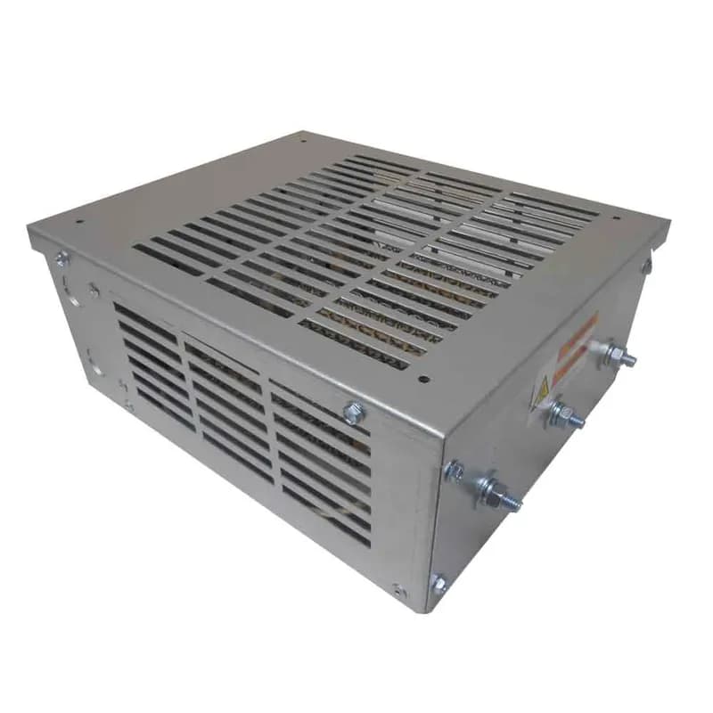
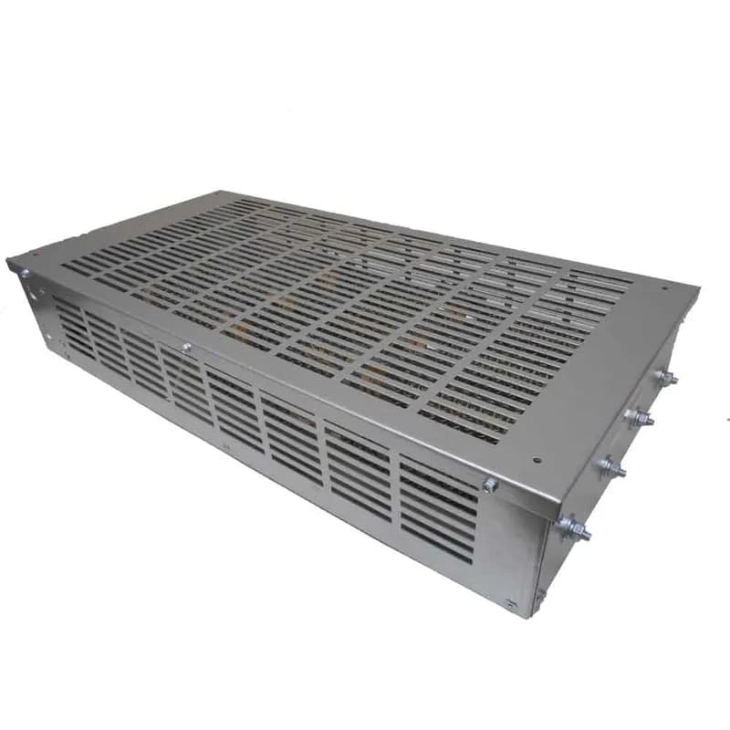
ABB Low Voltage Drives P14494-42 Braking Resistor, 21 OHMS, 1500 WATTS, GCE4 Enclosure, 12W x 13D x 5H in, 16 lbs
Alternate Item Number: 3AUA0000041892
UPC: 662348076347
Documents & Media
Contact for Pricing
Call +1 (262) 252-1600 (toll-free 877-268-3700) or email [email protected] for pricing and availability.
Overview
- 21 Ohm resistance for effective braking
- 1500 Watts continuous power dissipation
- Compact GCE4 enclosure (12"W x 13"D x 5"H)
- 16 lbs weight for easy installation
- Designed for ABB low-voltage drives
Specifications
Series | GCE4 |
Size | 12W x 13D x 5H in |




Frequently Asked Questions
What is the purpose of a braking resistor with variable frequency drives?
A braking resistor is required for applications needing faster deceleration or when motor speeds exceed synchronous speed. It increases braking torque and dissipates regenerated power to prevent bus voltage from exceeding drive limits.
When are braking modules used with braking resistors?
Braking modules are used with braking resistors to monitor the drive's DC bus and activate the resistor as needed to manage regenerated power and prevent over-voltage trips.
What is the purpose of the braking resistor in overhauling load conditions?
In overhauling load conditions, the braking resistor dissipates regenerated power flowing from the motor back into the drive, preventing the DC Bus from rising and causing an over-voltage trip.
How are Powerohm Type CR resistors constructed?
Type CR resistors use a nickel-chromium wire helically wound inside a ceramic fixture, housed in a corrosion-resistant aluminum case. Coil ends are terminated to high-temperature wire leads and encapsulated.
What is the function of the thermal switch in GCE and ED enclosures?
The normally closed thermal switch in GCE and ED enclosures is used to detect resistor temperature overloads.
What are the installation features of Type GCE enclosures?
Type GCE enclosures have a solid bottom and a built-in wiring compartment. Standard 90ºC rated wire can be routed through 1/2 inch conduit knockouts into the compartment.
What wire rating is required when attaching directly to resistors in Type ED enclosures?
If installing without optional terminal connections in Type ED enclosures, always use 200ºC rated silicone or Teflon wire when attaching directly to resistors.
What is the voltage range for ACS150 and ACS355 single-phase applications?
ACS150 and ACS355 single-phase applications are designed for 200-240V.
What is the voltage range for ACS150 and ACS355 three-phase applications?
ACS150 and ACS355 three-phase applications are designed for 200-240V and 380-480V.
What is the voltage range for ACS250 single-phase applications?
ACS250 single-phase applications are designed for 100-120V and 200-240V.