
ABB Low Voltage Drives ABB-42685 Braking Resistor, 1.72 OHMS, 21000 WATTS, ED2 Enclosure, 30W x 18D x 16H in, 89 lbs
Alternate Item Number: 3AUA0000015165
UPC: 662348000397
Documents & Media
Contact for Pricing
Call +1 (262) 252-1600 (toll-free 877-268-3700) or email [email protected] for pricing and availability.
Overview
- 21,000-watt power rating for high-energy braking applications
- 1.72Ω resistance optimized for ABB Low Voltage Drives compatibility
- ED2 enclosure rated for dust, water, and mechanical protection
- Compact 30W x 18D x 16H inch dimensions, 89 lbs weight
- Supports continuous operation at rated load for extended service life



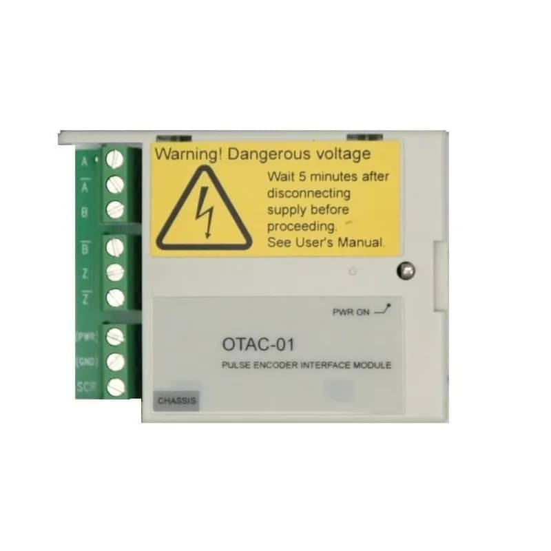
OTAC-01-KIT
The Pulse Encoder Interface module offers a differential or single ended interface for a digital pulse encoder connection. The module is capable of operating from either a 15 or 24 VDC signal with a maximum frequency of 200kHz.

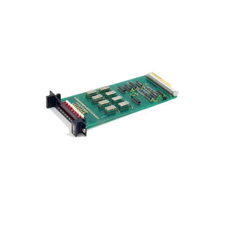
OREL-01-KIT
The Relay Output Extension module offers three (3) Form C relay outputs numbered RO 4, 5 and 6, rated 2 A maximum current. Switching capacity is 6 A (24 VDC resistive), 1500 VA (250 VAC), Each relay is galvanically isolated from each other (2.5 kVAC, 1 minute). Each relay is programmable.Frequently Asked Questions
What is the purpose of a braking resistor with a variable frequency drive?
A braking resistor is required for applications needing faster deceleration or when motor speeds exceed the drive's output frequency. It dissipates regenerated power to prevent bus voltage from exceeding the drive's rated limit.
What is the role of a braking chopper module?
Braking modules monitor the drive's DC bus and activate an external braking resistor as needed. This manages regenerated power and improves drive system performance.
How are Powerohm Type CR resistors constructed?
They feature a nickel-chromium wire helically wound inside a ceramic fixture, housed in a corrosion-resistant aluminum case. Coil ends are terminated to high-temperature wire leads and encapsulated with ceramic potting material.
What is the function of the thermal switch in Type GCE and ED enclosures?
The normally closed thermal switch detects resistor temperature overloads. It is used to monitor and alert if the resistor's temperature exceeds safe operating limits.
What wire is used for connections in Type GCE enclosures?
Standard 90ºC rated wire is used when routed into the compartment through the removable 1/2 inch conduit knockouts and connected to the factory wired terminal block.
What type of wire should be used when attaching directly to resistors in Type ED enclosures?
If installing without optional terminal connections, always use 200ºC rated silicone or Teflon wire when attaching directly to resistors.
What are the voltage and duty cycle for ACS150/355-01U drives with Type CR resistors?
These drives are for single-phase 200-240V applications and stopping duty only, with various duty cycles like 3sec on/27sec off, 10sec on/50sec off, 30sec on/180sec off, and 60sec on/180sec off.
What are the voltage and duty cycle for ACS150/355-03U drives with Type CR resistors?
These drives are for three-phase 200-240V applications and stopping duty only, with various duty cycles including 3sec on/27sec off, 10sec on/50sec off, 30sec on/180sec off, and 60sec on/180sec off.
What are the voltage and duty cycle for ACS150/355-03U drives with 380-480V applications?
These drives are for three-phase 380-480V applications and stopping duty only, with duty cycles such as 3sec on/27sec off, 10sec on/50sec off, 30sec on/180sec off, and 60sec on/180sec off.
What are the voltage and duty cycle for ACS250-01U drives with Type CR resistors?
These drives are for single-phase 100-120V applications and stopping duty only, with duty cycles including 3sec on/27sec off, 10sec on/50sec off, 30sec on/180sec off, and 60sec on/180sec off.