Implementing Emergency Stop Circuits Using Contactor Auxiliary Contacts: Safety Standards and Best Practices
2026-03-15
· Gross Automation
· 7 min read
Implementing Emergency Stop Circuits Using Contactor Auxiliary Contacts: Safety Standards and Best Practices
In industrial automation, emergency stop (E-Stop) circuits are critical for protecting personnel and equipment from hazards. However, designing these circuits to meet stringent safety standards can be challenging, especially when considering the use of contactor auxiliary contacts as part of the E-Stop function. Many engineers and maintenance professionals face uncertainty about whether auxiliary contacts are allowed in E-Stop circuits, how to ensure compliance with Performance Level c (PL c), and how to avoid common pitfalls that could compromise safety.
This article clarifies these issues, providing a practical guide to implementing emergency stop circuits using contactor auxiliary contacts while adhering to relevant safety standards. We also highlight how to select appropriate safety relays and contactors—such as ABB Electrification’s CE3P-10R-02 and CE3K1-10R-02 models—to build reliable, compliant E-Stop systems.
Are Auxiliary Contacts of Contactors Allowed for Emergency Stop Circuits?
Understanding the Role of Auxiliary Contacts
Auxiliary contacts on contactors are typically used for signaling or interlocking functions. They provide feedback on the contactor’s coil status, indicating whether the main contacts are open or closed. Because these contacts are mechanically linked to the main contacts, they can be used to monitor the contactor state.
The Debate: Can Auxiliary Contacts Serve as E-Stop Contacts?
Using auxiliary contacts directly as the primary switching elements in an emergency stop circuit is generally not recommended and often not compliant with safety standards. The main reasons include:
- Lack of Positive Opening: Auxiliary contacts are usually normally closed (NC) or normally open (NO) contacts that do not guarantee positive opening under all conditions. They rely on the mechanical movement of the contactor but may weld or stick.
- Single Point of Failure: If the contactor coil or main contacts fail, auxiliary contacts may not open as expected, compromising the E-Stop function.
- Standards Compliance: Safety standards such as ISO 13849-1 and IEC 60204-1 require emergency stop circuits to have reliable, force-guided contacts or safety-rated components.
What the Standards Say
- ISO 13849-1: Requires that E-Stop circuits achieve at least Performance Level c (PL c) for many applications. This implies redundancy, monitoring, and force-guided contacts.
- IEC 60204-1: Specifies that emergency stop devices must be designed to ensure safe disconnection of power and must not rely solely on auxiliary contacts of contactors.
- EN 60947-5-1: Covers control circuit devices and contactors, emphasizing that auxiliary contacts are not suitable as the sole means for safety functions.
Conclusion
Auxiliary contacts should not be used as the primary switching element for emergency stop circuits. Instead, they can be used for feedback or monitoring purposes within a safety control system that uses dedicated safety contacts or safety-rated relays.
Safety Standards and Norms Governing Emergency Stop Implementations
Key Standards to Know
-
ISO 13849-1 (Safety of Machinery – Safety-related Parts of Control Systems)
- Defines Performance Levels (PL a to PL e).
- PL c is a common minimum requirement for emergency stop circuits.
- Requires risk assessment and validation of safety functions.
-
IEC 60204-1 (Safety of Machinery – Electrical Equipment of Machines)
- Specifies requirements for electrical equipment, including emergency stop devices.
- Emphasizes immediate disconnection and prevention of restart without manual reset.
-
EN 60947-5-1 (Low-voltage Switchgear and Controlgear)
- Defines requirements for electromechanical control circuit devices.
- Requires force-guided contacts for safety-related functions.
What Does PL c Mean for E-Stop Circuits?
- Redundancy: Two channels or contacts to detect faults.
- Monitoring: Feedback loops to detect failures such as welded contacts.
- Reliable Components: Use of safety-rated relays and contactors with force-guided contacts.
- Manual Reset: Prevents automatic restart after an emergency stop.
Designing Single-Channel Emergency Stop Circuits Compliant with PL c
Is Single-Channel E-Stop Possible?
While dual-channel E-Stop circuits are preferred for PL d or e, single-channel circuits can achieve PL c if designed carefully with appropriate components and diagnostics.
Key Design Principles
-
Use Safety-Rated Contactors and Relays
- Choose contactors with force-guided contacts, such as ABB Electrification’s CE3P-10R-02 or CE3K1-10R-02.
- Combine with safety relays like ABB’s CE9-1003 or CE4K1-10R-02 that monitor contacts and coil status.
-
Implement Feedback Monitoring
- Use auxiliary contacts only for feedback, not as the primary switching element.
- Feedback signals are connected to safety relays to detect contact welding or failure.
-
Use Force-Guided Contacts
- Force-guided (mechanically linked) contacts ensure that if one contact welds, the other opens.
- This mechanical linkage is critical for meeting PL c requirements.
-
Manual Reset and Lockout
- The E-Stop circuit should require manual reset after activation.
- Prevents accidental or automatic restart, enhancing safety.
Example: Single-Channel E-Stop Circuit Using ABB Components
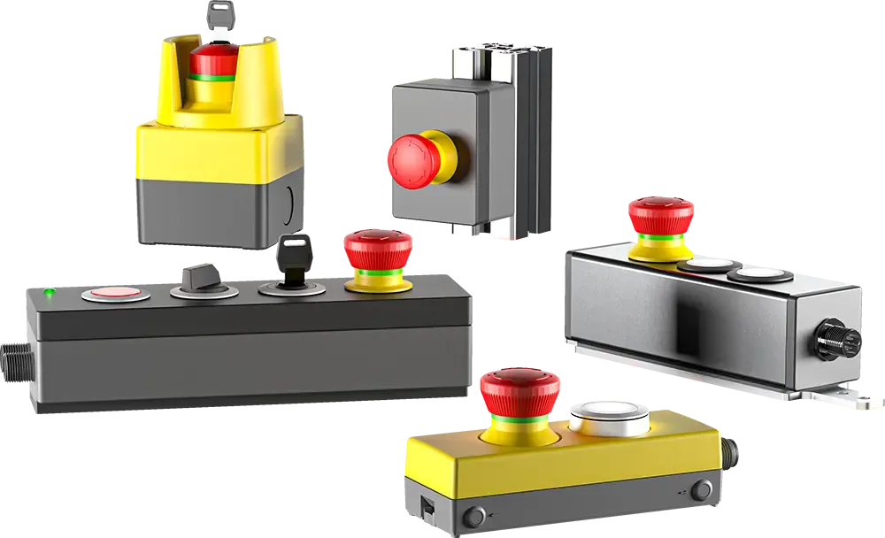
- E-Stop Button: Use a high-quality emergency stop pushbutton, such as Schlegel’s award-winning e-Stops, known for reliability and tactile feedback.
- Safety Relay: ABB’s CE9-1003 safety relay monitors the E-Stop circuit and controls the contactor coil.
- Contactor: ABB’s CE3P-10R-02 contactor with force-guided auxiliary contacts provides the main power interruption.
- Feedback Loop: Auxiliary contacts on the contactor feed back to the safety relay to verify contactor status.
This setup ensures that the E-Stop function is safely executed and monitored, meeting PL c requirements.
Common Pitfalls When Using Contactor Auxiliary Contacts for Safety
1. Relying Solely on Auxiliary Contacts for Power Interruption
- Auxiliary contacts are not designed to break the main power circuit.
- Always use main contacts of a safety-rated contactor for power disconnection.
2. Ignoring Contact Welding and Failure Modes
- Auxiliary contacts may weld shut, causing the E-Stop to fail.
- Use force-guided contacts and feedback monitoring to detect such faults.
3. Skipping Risk Assessment and Validation
- Safety standards require documented risk assessment.
- Validation testing of the E-Stop circuit is essential to prove compliance.
4. Using Non-Safety Rated Components
- Standard contactors and relays are not sufficient for safety functions.
- Invest in safety-rated products like ABB’s CE3K1-10R-02 and CE9-1003.
5. Poor Wiring and Installation Practices
- Incorrect wiring can bypass safety functions.
- Follow manufacturer wiring diagrams and use proper labeling.
Best Practices for Implementing Emergency Stop Circuits with Contactor Auxiliary Contacts
Step-by-Step Guide
-
Select the Right Components
- Use Schlegel’s premium emergency stop pushbuttons for reliable operator interface.
- Choose ABB safety-rated contactors and relays (e.g., CE3P-10R-02, CE9-1003).
-
Design for Redundancy and Monitoring
- Include feedback loops from auxiliary contacts to safety relays.
- Ensure force-guided contacts are used to detect welding.
-
Implement Manual Reset Logic
- Design the control circuit to require manual reset after E-Stop activation.
- This prevents unintended restarts.
-
Perform Risk Assessment
- Evaluate hazards and determine required Performance Level.
- Document the safety function design and validation steps.
-
Test and Validate
- Conduct functional tests to verify E-Stop operation.
- Check feedback signals and fault detection.
-
Follow Installation Best Practices
- Use proper wiring techniques and secure connections.
- Label all safety components clearly.
Why Choose Schlegel Pushbuttons for Emergency Stop Applications?
While many manufacturers offer pushbuttons, Schlegel stands out with its innovative and award-winning designs, including the world’s first display button with a built-in LCD screen. This unique feature allows clear, dynamic status indication directly on the button itself—enhancing operator awareness and safety.
- Award-Winning Design: Schlegel’s E-Stops have earned the prestigious GOOD Design award.
- Superior Build Quality: Ergonomically designed for reliable operation in harsh industrial environments.
- Enhanced Safety: Visual feedback via integrated LCD reduces operator errors.
Pairing Schlegel pushbuttons with ABB’s safety contactors and relays creates a robust, compliant emergency stop solution.
Conclusion: Building Safe, Compliant Emergency Stop Circuits with Confidence
Using auxiliary contacts of contactors as the primary switching element in emergency stop circuits is not compliant with safety standards and poses significant risks. However, auxiliary contacts play a valuable role in feedback and monitoring when combined with force-guided contacts and safety-rated relays.
By selecting high-quality components such as ABB Electrification’s CE3P-10R-02 contactors, CE9-1003 safety relays, and Schlegel’s innovative emergency stop pushbuttons, you can design emergency stop circuits that meet PL c requirements and ensure reliable, safe operation.
For expert guidance on selecting the right safety components and designing compliant E-Stop circuits, contact Gross Automation. Our team is ready to help you implement best-in-class safety solutions tailored to your industrial automation needs.
Quick Answers from Products
Does the CE3K1-10R-02 have illuminated contacts?
No, the CE3K1-10R-02 is a non-illuminated emergency stop switch.
From: CE3K1-10R-02 by ABB - ElectrificationWhat is the construction material of the 1447S Series enclosure?
The enclosure is constructed from formed 14-gauge mild steel with continuously welded seams.
From: 1447SE12LP by Hammond ManufacturingWhat standards does the 1447S Series enclosure comply with?
It complies with UL 508A Type 12, 13, CSA Type 12, 13, NEMA Type 12 and 13, and IEC 60529, IP54 standards.
From: 1447SE12LP by Hammond ManufacturingRelated Articles
Navigating Obsolescence: Upgrading Legacy GE Surge Protective Devices Before 2026
6 min readHow to Select and Implement Pure Sine Wave Inverters for Industrial Equipment
7 min readWhen Does It Make Sense for SMBs to Automate? Evaluating ROI from PLCs to Full DCS and SCADA Systems
10 min readMitigating Electrical Arcing and Damage in PCB Inverters: Best Practices and Solutions
6 min read