Showing 1-12 of 13 results
Contact for Pricing
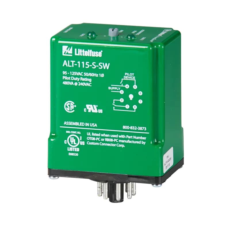
The ALT alternating relays are used to alternate between two loads. The ALT is commonly used in duplex pumping applications to balance the runtime of both pumps. The ALT-S is used in single high-level float applications. When the float switch opens, the alternating relay changes state, forcing the other pump to run the next time the float closes. All ALT relays have a built-in debounce feature that prevents the relay from changing state if the switch or float contact bounces momentarily. The ALT-X has an internal cross-connected relay and is used in dual high-level float applications. These floats are commonly referred to as lead and lag floats. The pumps alternate as in the ALT-S version but the crossconnected relay configuration allows both pumps to run simultaneously when both the lead and lag floats are closed. These relays are also available with a built-in switch (SW option) that is used to manually force one of the pumps to run every time the float switch is closed. This is helpful when a pump has been removed for repair or for test purposes. In the case of the ALT-X-SW, the switch essentially forces one pump to be the lead pump, while still allowing the second to run when both floats are closed. Must use the OT08PC socket for UL Rating!
Contact for Pricing
The ALT alternating relays are used to alternate between two loads. The ALT is commonly used in duplex pumping applications to balance the runtime of both pumps. The ALT-S is used in single high-level float applications. When the float switch opens, the alternating relay changes state, forcing the other pump to run the next time the float closes. All ALT relays have a built-in debounce feature that prevents the relay from changing state if the switch or float contact bounces momentarily. The ALT-X has an internal cross-connected relay and is used in dual high-level float applications. These floats are commonly referred to as lead and lag floats. The pumps alternate as in the ALT-S version but the crossconnected relay configuration allows both pumps to run simultaneously when both the lead and lag floats are closed. These relays are also available with a built-in switch (SW option) that is used to manually force one of the pumps to run every time the float switch is closed. This is helpful when a pump has been removed for repair or for test purposes. In the case of the ALT-X-SW, the switch essentially forces one pump to be the lead pump, while still allowing the second to run when both floats are closed. Must use the OT08PC socket for UL Rating!
Contact for Pricing
Contact for Pricing

Contact for Pricing
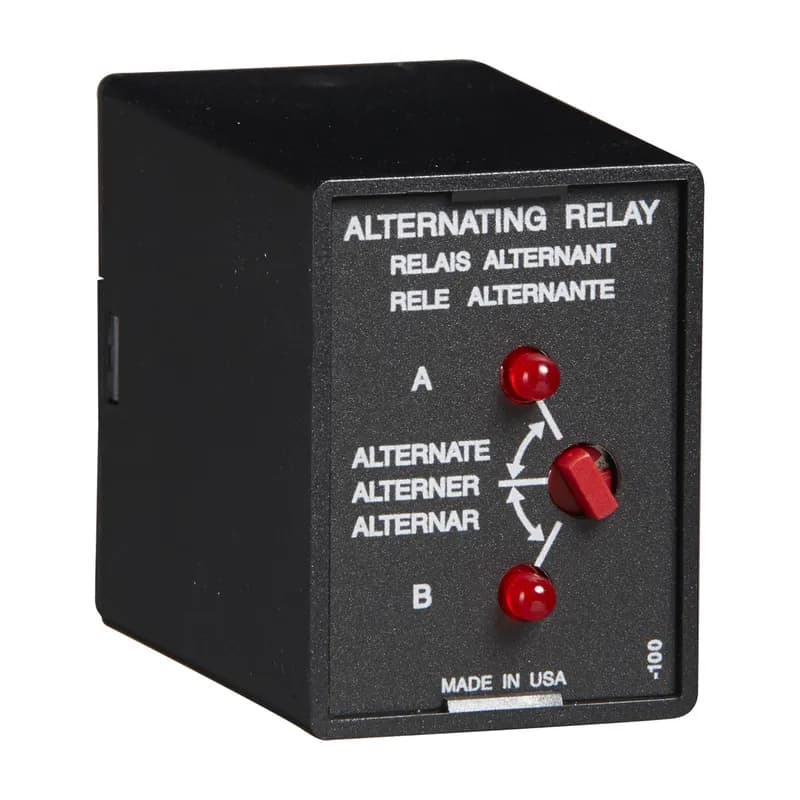
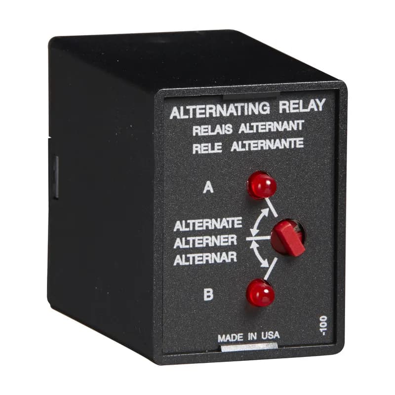
The ARP Series is used in systems where equal run time for two motors is desirable. The selector switch allows selection of alternation of either load for continuous operation. LED’s indicate the status of the output relay. This versatile series may be front panel mounted (BZ1 accessory required) or 35 mm DIN rail mounted with an accessory socket. Operation: Alternating: When the rotary switch is in the “alternate” position, alternating operation of Load A and Load B occurs upon the opening of the control switch S1. To terminate alternating operation and cause only the selected load to operate, rotate the switch to position “A” to lock Load A or position “B” to lock Load B. The LEDs indicate the status of the internal relay and which load is selected to operate. Note: Input voltage must be applied at all times for proper alternation. The use of a solid-state control switch for S1 may not initiate alternation correctly. S1 voltage must be from the same supply as the unit’s input voltage (see connection diagrams on datasheet). Loss of input voltage resets the unit; Load A becomes the lead load for the next operation. Duplexing (Cross Wired): Duplexing models operate the same as alternating relays and when both the Control (S1) and Lag Load (S2) Switches are closed, Load A and Load B energize simultaneously. The DPDT 8-pin, cross-wired option, allows extra system load capacity through simultaneous operation of both motors when needed. Relay contacts are not isolated.
Contact for Pricing
The ARP Series is used in systems where equal run time for two motors is desirable. The selector switch allows selection of alternation of either load for continuous operation. LED’s indicate the status of the output relay. This versatile series may be front panel mounted (BZ1 accessory required) or 35 mm DIN rail mounted with an accessory socket. Operation: Alternating: When the rotary switch is in the “alternate” position, alternating operation of Load A and Load B occurs upon the opening of the control switch S1. To terminate alternating operation and cause only the selected load to operate, rotate the switch to position “A” to lock Load A or position “B” to lock Load B. The LEDs indicate the status of the internal relay and which load is selected to operate. Note: Input voltage must be applied at all times for proper alternation. The use of a solid-state control switch for S1 may not initiate alternation correctly. S1 voltage must be from the same supply as the unit’s input voltage (see connection diagrams on datasheet). Loss of input voltage resets the unit; Load A becomes the lead load for the next operation. Duplexing (Cross Wired): Duplexing models operate the same as alternating relays and when both the Control (S1) and Lag Load (S2) Switches are closed, Load A and Load B energize simultaneously. The DPDT 8-pin, cross-wired option, allows extra system load capacity through simultaneous operation of both motors when needed. Relay contacts are not isolated.
Contact for Pricing
The ARP Series is used in systems where equal run time for two motors is desirable. The selector switch allows selection of alternation of either load for continuous operation. LED’s indicate the status of the output relay. This versatile series may be front panel mounted (BZ1 accessory required) or 35 mm DIN rail mounted with an accessory socket. Operation: Alternating: When the rotary switch is in the “alternate” position, alternating operation of Load A and Load B occurs upon the opening of the control switch S1. To terminate alternating operation and cause only the selected load to operate, rotate the switch to position “A” to lock Load A or position “B” to lock Load B. The LEDs indicate the status of the internal relay and which load is selected to operate. Note: Input voltage must be applied at all times for proper alternation. The use of a solid-state control switch for S1 may not initiate alternation correctly. S1 voltage must be from the same supply as the unit’s input voltage (see connection diagrams on datasheet). Loss of input voltage resets the unit; Load A becomes the lead load for the next operation. Duplexing (Cross Wired): Duplexing models operate the same as alternating relays and when both the Control (S1) and Lag Load (S2) Switches are closed, Load A and Load B energize simultaneously. The DPDT 8-pin, cross-wired option, allows extra system load capacity through simultaneous operation of both motors when needed. Relay contacts are not isolated.
Contact for Pricing
The ARP Series is used in systems where equal run time for two motors is desirable. The selector switch allows selection of alternation of either load for continuous operation. LED’s indicate the status of the output relay. This versatile series may be front panel mounted (BZ1 accessory required) or 35 mm DIN rail mounted with an accessory socket. Operation: Alternating: When the rotary switch is in the “alternate” position, alternating operation of Load A and Load B occurs upon the opening of the control switch S1. To terminate alternating operation and cause only the selected load to operate, rotate the switch to position “A” to lock Load A or position “B” to lock Load B. The LEDs indicate the status of the internal relay and which load is selected to operate. Note: Input voltage must be applied at all times for proper alternation. The use of a solid-state control switch for S1 may not initiate alternation correctly. S1 voltage must be from the same supply as the unit’s input voltage (see connection diagrams on datasheet). Loss of input voltage resets the unit; Load A becomes the lead load for the next operation. Duplexing (Cross Wired): Duplexing models operate the same as alternating relays and when both the Control (S1) and Lag Load (S2) Switches are closed, Load A and Load B energize simultaneously. The DPDT 8-pin, cross-wired option, allows extra system load capacity through simultaneous operation of both motors when needed. Relay contacts are not isolated.
Contact for Pricing
Contact for Pricing
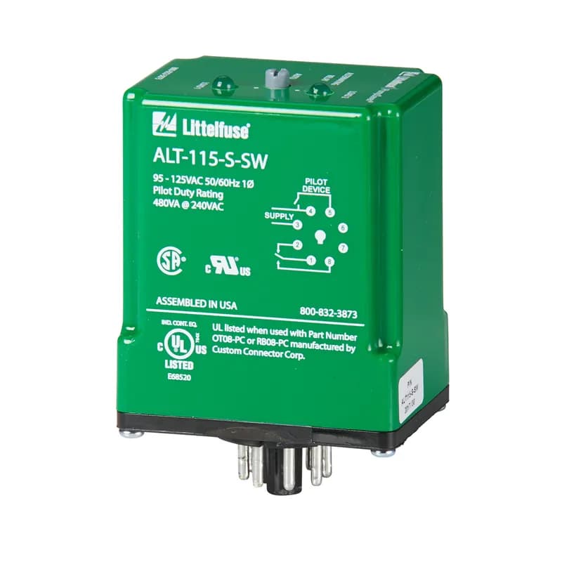
The ALT alternating relays are used to alternate between two loads. The ALT is commonly used in duplex pumping applications to balance the runtime of both pumps. The ALT-S is used in single high-level float applications. When the float switch opens, the alternating relay changes state, forcing the other pump to run the next time the float closes. All ALT relays have a built-in debounce feature that prevents the relay from changing state if the switch or float contact bounces momentarily. The ALT-X has an internal cross-connected relay and is used in dual high-level float applications. These floats are commonly referred to as lead and lag floats. The pumps alternate as in the ALT-S version but the crossconnected relay configuration allows both pumps to run simultaneously when both the lead and lag floats are closed. These relays are also available with a built-in switch (SW option) that is used to manually force one of the pumps to run every time the float switch is closed. This is helpful when a pump has been removed for repair or for test purposes. In the case of the ALT-X-SW, the switch essentially forces one pump to be the lead pump, while still allowing the second to run when both floats are closed. Must use the OT08PC socket for UL Rating!
Contact for Pricing
The ALT alternating relays are used to alternate between two loads. The ALT is commonly used in duplex pumping applications to balance the runtime of both pumps. The ALT-S is used in single high-level float applications. When the float switch opens, the alternating relay changes state, forcing the other pump to run the next time the float closes. All ALT relays have a built-in debounce feature that prevents the relay from changing state if the switch or float contact bounces momentarily. The ALT-X has an internal cross-connected relay and is used in dual high-level float applications. These floats are commonly referred to as lead and lag floats. The pumps alternate as in the ALT-S version but the crossconnected relay configuration allows both pumps to run simultaneously when both the lead and lag floats are closed. These relays are also available with a built-in switch (SW option) that is used to manually force one of the pumps to run every time the float switch is closed. This is helpful when a pump has been removed for repair or for test purposes. In the case of the ALT-X-SW, the switch essentially forces one pump to be the lead pump, while still allowing the second to run when both floats are closed. Must use the OT08PC socket for UL Rating!
Contact for Pricing
Showing 1-12 of 13 results