Contact for Pricing
Minimum Qty: 4
Multiplier: 4
*Contact for lower quantities*
Overview
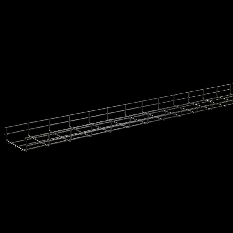
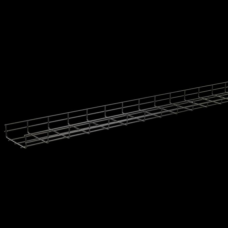
- Durable steel construction with light gray finish for corrosion resistance and longevity.
- 4-inch by 18-inch dimensions provide ample capacity for diverse cable loads.
- Open wire mesh design ensures excellent ventilation, reducing heat buildup and protecting cables.
- Quick and easy installation with integrated splice system, minimizing labor costs.
- Versatile system components allow for custom configurations to suit any application.
- Ideal for industrial, commercial, data center, and telecommunications environments.
- Maintains cable accessibility for efficient maintenance and future upgrades.
Specifications
Application | Networking, Storage and Data Center |
Cable Quantity, Cat 6 @75% Fill | 942 |
Color | Unpainted |
Color | Light Gray |
Color | Lt Gray |
Fill Rate, Cat 6 diam. 0.19 in | 942 |
Fill Rate, Cat 6A diam. 0.23 in | 862 |
Load | 116 lb/ft |
Load Per 6 ft Span | 116 lb/ft |
Material | Steel |
Modification Services | No |
Mounting Type | Modular System Mounting |
Nominal Width | 18 in |
Product Family | QuickTray Pro |
Series | Quick Tray Pro |
Size | 4.00x18.00x120.00 |
Size | 4.00x18.00x120.00 in |
Splice Quantity | 7 |
Splice Quantity, Per Joint | 7 |
Thickness | 0.2 in |
Type | Cable Pathway |
Weight | 23 lb |
Weight Per Section | 29 lb |
Package Dimensions (L x W x H) | 120 IN x 18.75 IN x 9.25 IN |
Package Dimensions (L x W x H) | 304.8 cm x 47.625 cm x 23.495 cm |
Package Weight (Imperial) | 23.000 L |
Package Weight (Metric) | 10.433 kg |

How to Install and Configure QUICK TRAY PRO Cable Tray Sections
This guide provides comprehensive instructions for modifying, connecting, and supporting QUICK TRAY PRO cable tray sections to create custom cable routing solutions for models like QTP4X18.
Estimated time: 2h
Tools needed:
Hoffman side action bolt cutter
Supplies needed:
QUICK TRAY PRO Cable Tray sections, Splice Kits (QTPBNWK/QTPBNWKBLK), Splice Washers (QTPSSW3/QTPSSW3BLK), Universal Splice Bars (QTPUS10/QTPUS10BLK), T-Connection or 90o Splice Bars (QTP90TKIT/QTP90TKITBLK), Cable tray supports
- Plan Your Cable Tray Layout and Mark Cuts
Before cutting, carefully plan the desired cable tray configuration, including straight runs, bends, and tees. Review the appropriate cutting patterns for your tray size and desired shape as shown in the manual. Mark the wires that need to be removed or cut on the cable tray sections.
- Cut Cable Tray Sections to Size
Use the Hoffman side action bolt cutter to make precise cuts. For side wires, position the cutting jaws on the cradle wire and cut at an angle away from the new end. For bottom wires, turn the tray over, rest the cutting jaws on the cradle wire, and cut at an angle away from the new end. Ensure each cut is clean to minimize sharp edges and protect against corrosion.
- Form Bends, Tees, or Reductions (as required)
To create a 90-degree bend, cut the specified side and bottom wires, then smoothly bend the tray until the inside edges meet. For large radius bends, remove outside and bottom wires from alternating mesh sections and gently pull the ends together. For tees or width reductions, follow the specific cutting patterns and use appropriate splice bars (Universal or T-Connection) to form the desired shape.
- Join Cable Tray Sections
Align the ends of the cable tray sections to be joined. Securely fasten them together using Splice Kits (QTPBNWK/QTPBNWKBLK) and Splice Washers (QTPSSW3/QTPSSW3BLK). For straight connections, ensure adequate support. For elbows or tees, use the specified number of splice kits and washers to create a strong, stable joint at the desired angle.
- Install Supports for the Cable Tray System
Install straight section supports at typical 6-foot (1.5m) centers. Ensure supports are placed within 24 inches (610mm) of any splice on straight sections. The span between supports must not exceed the length of the tray. Provide additional supports around all bends and wherever the cable tray changes levels to maintain stability and load capacity.
Frequently Asked Questions about nVent
What industries and applications are nVent products used for?
nVent products are engineered for critical infrastructure and industrial applications across multiple demanding sectors. Key markets include Construction, Data Centers, Defense, Healthcare, Mining, Oil & Gas Refineries, Power Plants, Rail/Transit, Renewable Energy, Security, Ship Building, Steel Mills, Telecom, and Utilities. Their solutions are designed to withstand extreme environmental conditions, with temperature ranges from -55°C to 105°C and specialized features like UV resistance, oil resistance, and flame resistance.
What environmental ratings do nVent products have?
nVent enclosures feature comprehensive environmental ratings, including UL 508A, CSA, and NEMA Type 1, 2, 3, 4, 4X, 12, and 13 certifications. They are rated IEC 60529 IP66, providing robust protection against dust, water, and corrosion in both indoor and outdoor environments. These products operate effectively in temperatures ranging from -40°F to 266°F, with enhanced UV inhibitors for outdoor weathering and oil-resistant gaskets for superior sealing.
What accessories are available for nVent products?
nVent offers a comprehensive range of accessories across multiple product lines, including EMC accessories like bonding cable clamps and strain reliefs, inline accessories such as lock inserts and mounting brackets, CONCEPT accessories including panel conversion kits and rack-mount angles, and seismic accessories for specialized mounting requirements. Key accessory categories include grounding kits, DIN rail mounting solutions, panel supports, handles, and various mounting hardware compatible with different enclosure types.
What certifications and standards do nVent products comply with?
nVent products meet critical international certifications including UL (United States), CSA (Canada), CE (European Community), and EAC (Russia). Our products are designed to comply with rigorous industrial standards such as NEMA enclosure ratings, IEC 60529 IP ratings, and international safety standards across multiple industrial markets including oil & gas, power, manufacturing, and infrastructure.
What is nVent's warranty policy?
nVent offers a standard 18-month warranty from invoicing date for most automation products, covering defects in workmanship and materials. The warranty requires proper transportation, handling, storage, and installation within specified environmental conditions. Warranty coverage includes repair or replacement at nVent's discretion, with certain conditions such as authorized service repairs and operation within designed capacity limits.
What technical support does nVent offer?
nVent offers comprehensive technical support through multiple global contact centers across North America, South America, Europe, Middle East, India, and Asia. Customers can reach technical experts by phone at regional numbers, with the North American headquarters in Minneapolis, MN providing primary support at +1.763.421.2240. Additionally, nVent provides online support resources through their website, including CAD drawing downloads and an 'Ask The Expert' feature to assist with product technical inquiries.