
nVent A21ITE Operator Adapter Universal Cutout, I-T-E Max-flex, Gray, Steel
UPC: 783510297602
Documents & Media
Contact for Pricing
Call +1 (262) 252-1600 (toll-free 877-268-3700) or email [email protected] for pricing and availability.
Overview
- Universal cutout compatible with Bulletin A21, A28, A34, and A4L3D HOFFMAN enclosures
- Available in small and large handle sizes for disconnect switches and circuit breakers
- Gray steel construction with powder-coated finish for durability
- Ensures proper interlocking between enclosure door and disconnect mechanism
- Manufactured in the US with included installation instructions
- A 400A (or greater) disconnect switch and 600A (or greater) circuit breaker require the large handle
- A 200A (or less) disconnect switch and 400A (or less) circuit breaker require a small handle
Specifications
Color | Gray |
Current Rating | 200A or less (small handle), 400A or greater (large handle) |
Ip Rating | Type 4 and Type 12 |
Material | Steel |
Mounting Type | Universal flange cutout |
Nema Rating | Type 4 and Type 12 |
Series | I-T-E Max-flex |
Package Dimensions (L x W x H) | 19.25 IN x 4.25 IN x 4.75 IN |
Package Dimensions (L x W x H) | 48.895 cm x 10.795 cm x 12.065 cm |
Package Weight (Imperial) | 2.780 L |
Package Weight (Metric) | 1.261 kg |


P10084C
10x8x4 Polycarbonate Enclosure NEMA 6P | Standard Hinge | Clear Lid | Integrated Locking Latch | Intergrated Mounting Flange
TGL6
No matter the application, we’ve got you covered with a rugged, reliable and easy-to-install Spec-Setter safety switch. EQUIPMENT GROUND KIT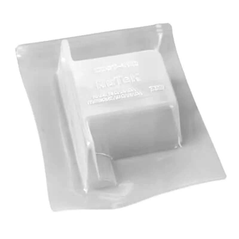

RCR75J
A retrofit cable connector for nonmetallic sheathed cable and NM-B nonmetallic cable. It is made of plastic and comes in grey. The size is 3/4" and it is designed for 1-cable use.
How to Install the A21ITE Operator Adapter for I-T-E MAX-FLEX Disconnects
This guide details the installation of the A21ITE Operator Adapter for I-T-E MAX-FLEX mechanisms in Hoffman enclosures with the disconnect on the right flange. Be certain to check the function, fits, and clearances of all equipment both before and after installation to assure proper and safe operation, meeting all applicable codes and standards.
Estimated time: 1h
Tools needed:
Screwdriver, Wrench, Drill, Tap set
Supplies needed:
Adapter Plate (Item 1 or 15), Plate Gasket (Item 2), Screws (Item 3, 6 or 18, 12), Slide Arm (Item 4 or 16), Shoulder Collar (Item 5 or 17), Lockwashers (Item 7 or 19, 9, 13), Flat Washers (Item 8), Hex Nuts (Item 10), Door Catch (Item 11), I-T-E operating handle, I-T-E interlock lever extension, Panel, Disconnect switch or circuit breaker
- Install Adapter Plate and Gasket
Install the appropriate adapter plate (item 1 or 15) and plate gasket (item 2) on the inside of the enclosure. Position it behind the rectangular opening provided and secure it in place with four screws (item 3).
- Assemble I-T-E Operating Handle
Assemble the I-T-E operating handle to the adapter plate that was installed in Step 1. Omit the cap screw and lockwasher that typically fit into the bottom hole of the I-T-E operating handle, as these will be used in the next step.
- Install Slide Arm and Shoulder Collar
Position the slide arm (item 4 or 16) over the interlock lever part of the I-T-E operating handle, ensuring the notch in the slide arm is positioned toward the door opening. Place the smaller diameter end of the shoulder collar (item 5 or 17) through the oval slot in the slide arm. Install the long cap screw (item 6 or 18) with lockwasher (item 7 or 19) through the shoulder collar into the bottom mounting hole of the I-T-E operating handle and tighten. Verify the slide arm moves up and down smoothly. Install the interlock lever extension per I-T-E instructions.
- Connect Slide Arm to Lock Release Mechanism
Attach the bottom of the slide arm to the offset arm of the lock release mechanism. Use two flat washers (item 8), two lockwashers (item 9), and two hex nuts (item 10). Do not fully tighten these fasteners yet, as adjustments will be made in a later step.
- Adjust Safety Lock Release Mechanism
Adjust the handle safety lock release mechanism in two places. First, check the factory-installed roller bracket; the door latch should hit against the latch stop portion of the roller bracket when the door is closed and latched. Adjust up or down if necessary. Second, adjust the length of the slide arm assembly. With proper adjustment, the safety lock (in the I-T-E operating handle) should release just before the master door is fully latched. Lengthen the slide arm if the safety lock releases too soon, or shorten it if it releases too late. Once adjusted, tighten the fasteners from Step 4.
- Install and Adjust Door Catch
Attach the door catch (item 11), provided by Hoffman, to the tapped spacer on the door using the bottom set of mounting holes. Use two screws (item 12) and lockwashers (item 13). Adjust the door catch up or down to ensure it hooks properly on the interlock blade. The door catch must be positioned so it just clears the top of the interlock lever extension when the I-T-E operating handle is in the extreme “OFF” position. This prevents the door from being opened when the I-T-E operating handle is in the “ON” position.
- Prepare Panel for Disconnect
Drill and tap holes in the panel as shown in the provided diagrams and tables (e.g., Table 1 for disconnect switches or circuit breakers). Refer to the I-T-E instructions for specific hole patterns and ensure the disconnect can be located anywhere within reach of the cable length being used.
- Install Panel
Install the prepared panel onto the collar studs inside the enclosure.
- Mount Disconnect Switch or Circuit Breaker
Mount the disconnect switch or circuit breaker and its operating mechanism onto the installed panel. Use the I-T-E instructions and parts for this mounting procedure.
Frequently Asked Questions about nVent
What industries and applications are nVent products used for?
nVent products are engineered for critical infrastructure and industrial applications across multiple demanding sectors. Key markets include Construction, Data Centers, Defense, Healthcare, Mining, Oil & Gas Refineries, Power Plants, Rail/Transit, Renewable Energy, Security, Ship Building, Steel Mills, Telecom, and Utilities. Their solutions are designed to withstand extreme environmental conditions, with temperature ranges from -55°C to 105°C and specialized features like UV resistance, oil resistance, and flame resistance.
What environmental ratings do nVent products have?
nVent enclosures feature comprehensive environmental ratings, including UL 508A, CSA, and NEMA Type 1, 2, 3, 4, 4X, 12, and 13 certifications. They are rated IEC 60529 IP66, providing robust protection against dust, water, and corrosion in both indoor and outdoor environments. These products operate effectively in temperatures ranging from -40°F to 266°F, with enhanced UV inhibitors for outdoor weathering and oil-resistant gaskets for superior sealing.
What accessories are available for nVent products?
nVent offers a comprehensive range of accessories across multiple product lines, including EMC accessories like bonding cable clamps and strain reliefs, inline accessories such as lock inserts and mounting brackets, CONCEPT accessories including panel conversion kits and rack-mount angles, and seismic accessories for specialized mounting requirements. Key accessory categories include grounding kits, DIN rail mounting solutions, panel supports, handles, and various mounting hardware compatible with different enclosure types.
What certifications and standards do nVent products comply with?
nVent products meet critical international certifications including UL (United States), CSA (Canada), CE (European Community), and EAC (Russia). Our products are designed to comply with rigorous industrial standards such as NEMA enclosure ratings, IEC 60529 IP ratings, and international safety standards across multiple industrial markets including oil & gas, power, manufacturing, and infrastructure.
What is nVent's warranty policy?
nVent offers a standard 18-month warranty from invoicing date for most automation products, covering defects in workmanship and materials. The warranty requires proper transportation, handling, storage, and installation within specified environmental conditions. Warranty coverage includes repair or replacement at nVent's discretion, with certain conditions such as authorized service repairs and operation within designed capacity limits.
What technical support does nVent offer?
nVent offers comprehensive technical support through multiple global contact centers across North America, South America, Europe, Middle East, India, and Asia. Customers can reach technical experts by phone at regional numbers, with the North American headquarters in Minneapolis, MN providing primary support at +1.763.421.2240. Additionally, nVent provides online support resources through their website, including CAD drawing downloads and an 'Ask The Expert' feature to assist with product technical inquiries.