
ABB Low Voltage Drives P14494-59 Braking Resistor, 10 OHMS, 3600 WATTS, GCE6 Enclosure, 19W x 10D x 5H in, 19 lbs
Alternate Item Number: 3AUA0000041891
UPC: 662348076491
Documents & Media
Contact for Pricing
Call +1 (262) 252-1600 (toll-free 877-268-3700) or email [email protected] for pricing and availability.
Overview
- 10 Ohm resistance for effective energy dissipation
- 3600 Watt power rating for high-demand applications
- GCE6 enclosure for robust industrial protection
- Compact dimensions: 19" W x 10" D x 5" H
- Designed for compatibility with ABB Low Voltage Drives
Specifications
Mounting Type | Panel or Wall Mounting |
Series | GCE6 |
Size | 19W x 10D x 5H in |

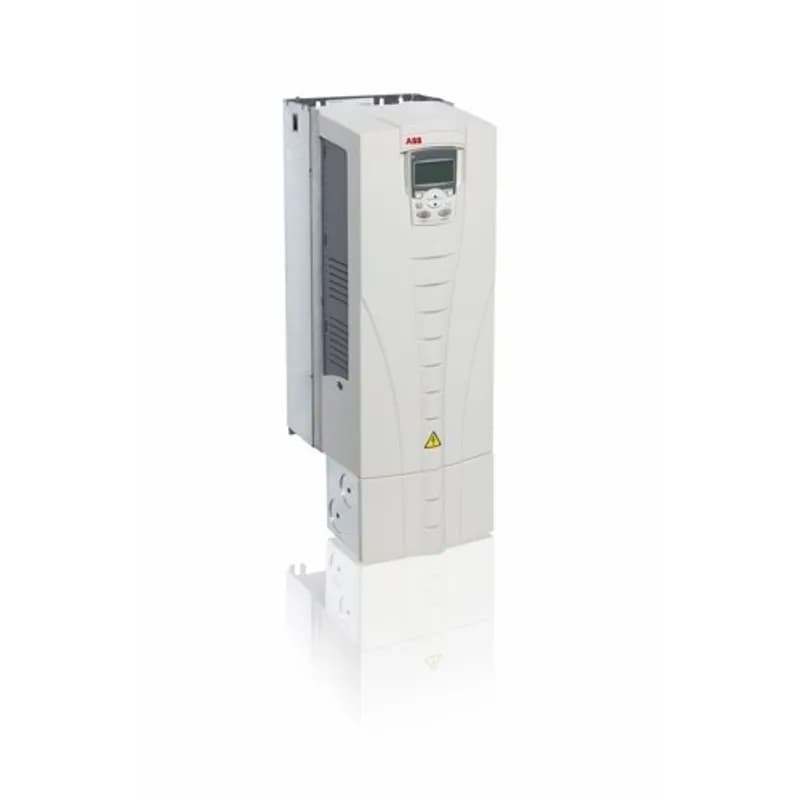
ACS550-DEMOCASE
Powered by 115VAC, the ACS550 DemoCase includes an ACS550 drive mounted on a panel. Included is a motor and I/O board with switches, pots, meters and LEDs permitting remote operation of the drive and motor.
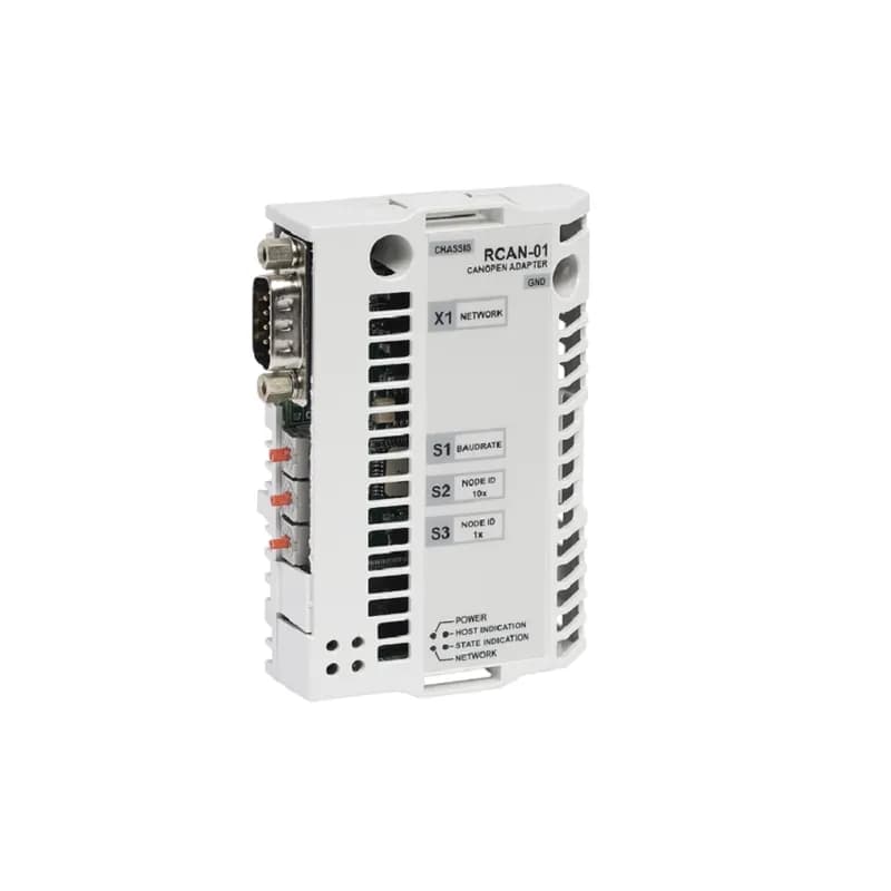
RCAN-01-KIT
CANopen is a higher layer protocol based on the CAN (Control Area Network) serial bus system and the CAL (CAN Application Layer). CANopen assumes that the hardware of the connected device has a CAN transceiver and a CAN controller as specified in ISO 11898.The CANopen Communication Profile, CiA DS 301, includes both cyclic and event driven communication, which makes it possible to reduce the bus load to minimum while still maintaining extremely short reaction times. High communication performance can be achieved at relatively low baud rates, thus reducing EMC problems and cable costs. CANopen device profiles define both direct access to drive parameter and time critical process data communication. The RCAN-01 module fulfills Cia (CAN in Automation) standard DSP 402 (Drives and Motion Control).
RDCO-01C-KIT
The RDCO-01 module includes the connectors for fiber optic DDCS channels CH0, CH1, CH2 and CH3. The usage of these channels is determined by the application but are normally assigned to the following: CH0 – overriding system (e.g. fieldbus adapter) - 10 MBd. CH1 – I/O extensions - 5MBd. CH2 – Master/Follower link - 10 MBd. CH3 – PC tools (such as DriveWare) - 10 MBd.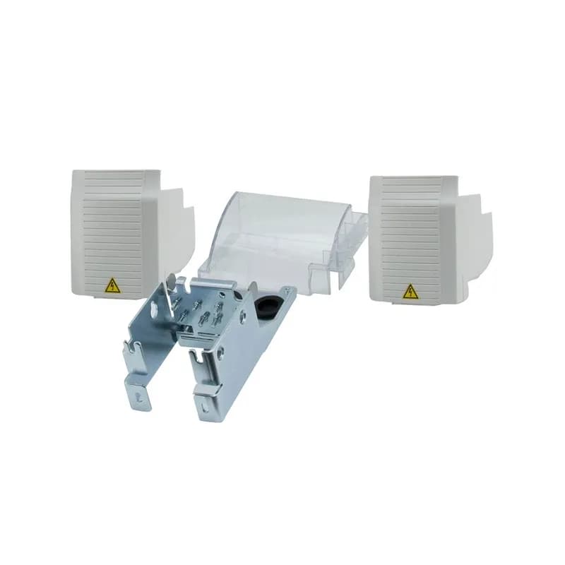
MUL1-R3
This option provides the necessary hardware to modify the ACS310, ACS350 or ACS355 drive from the standard fingersafe protected chassis to NEMA 1 protection capable of landing conduit. MUL1 R3 is used with frame size R3.Frequently Asked Questions
What is the resistance and wattage for P14494-59 resistor for a 15 Hp ACS150/355-03U-46A2-2 drive?
For a 15 Hp ACS150/355-03U-46A2-2 drive, the P14494-59 resistor has 10 Ohms and 3600 Watts for a 60sec on/180sec off duty cycle.
What is the resistance and wattage for P14494-32 resistor for a 3 Hp ACS250-03U-10A5-2 drive?
For a 3 Hp ACS250-03U-10A5-2 drive, the P14494-32 resistor has 50 Ohms and 400 Watts for a 60sec on/180sec off duty cycle.
What is the resistance and wattage for P14494-75 resistor for a 50 Hp ACS550-U1-143A-2 drive?
For a 50 Hp ACS550-U1-143A-2 drive, the P14494-75 resistor has 3.3 Ohms and 4316 Watts for a 3sec on/27sec off duty cycle.
What are the resistance and wattage for P14494-CR-02 resistor for a 0.5 Hp ACS150/355-01U-02A4-2 drive?
For a 0.5 Hp ACS150/355-01U-02A4-2 drive, the P14494-CR-02 resistor has 200 Ohms and 100 Watts for various duty cycles.
What is the resistance and wattage for P14494-CR-03 resistor for a 2 Hp ACS250-03U-04A1-4 drive?
For a 2 Hp ACS250-03U-04A1-4 drive, the P14494-CR-03 resistor has 150 Ohms and 100 Watts for a 3sec on/27sec off duty cycle.
What is the resistance and wattage for P14494-CR-04 resistor for a 1 Hp ACS550-U1-04A6-2 drive?
For a 1 Hp ACS550-U1-04A6-2 drive, the P14494-CR-04 resistor has 100 Ohms and 100 Watts for a 3sec on/27sec off duty cycle.
What are the voltage and application type for ACS250-03U-04A1-4 drives with Type CR resistors?
These drives are for three-phase 380-480V applications and are for stopping duty only.
Which ABB drives are compatible with Type CR resistors for single-phase 200-240V applications?
ACS150 and ACS355 drives are compatible for single-phase 200-240V applications, for stopping duty only.
What is the purpose of a braking resistor with variable frequency drives?
Braking resistors dissipate regenerated power to prevent bus voltage from exceeding the drive's rated limit, increasing braking torque for faster, controlled deceleration.
What is the purpose of braking choppers (modules)?
Braking modules monitor the drive's DC bus and activate external braking resistors to manage regenerated power and avoid over-voltage trips.